


E-5
Printer table
Back (short)
Front (long)
Side bar
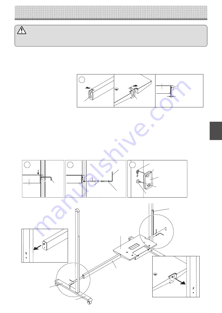
CAUTION
• Lock the casters of the T-shaped feet (left and right). If not, the stand could slip, causing the stand or main
unit to fall and resulting in injury or damage.
1
. Mount the T-shaped feet to the side bar.
The shorter side of the T-shaped foot is the back of the stand. The diagrams show the procedure from the back side.
Set the T-shaped foot with the cable cover on the right side (the printer table side).
Remove the temporary fixing tape from the ends of the side bar.
Insert the side bar's screw head into the T-shaped foot's screw hole (on the top), slide downwards, then use the
hexagonal wrench to partially fasten.
Insert the M5 x 45 screw and Plain washer into the sleeve, then use the hexagonal wrench to partially fasten it to
the side bar.
• Check that the sleeve is not sticking out.
• Once mounting of the left and right T-shaped feet is completed, tighten the four screws, adjusting so there is
no looseness.
Fasten the screw caps to the screw heads of the left and right T-shaped feet.
A. With the screw caps set slightly at an angle, place the hooks into the screw holes in the T-shaped feet and
slide downwards.
B: Press the stoppers of the screw caps into the hollows in the M5 screw heads.
4. ASSEMBLY OF THE STAND
Screw cap
Screw hole
A. Hook
B. Stopper
M5 screw head
2
3
4
Side bar
Hexagonal
wrench
Hexagonal
wrench
Sleeve
Plain washer
M5 x 45 mm screw
1
M5 screw
(mounted on
side bar)
Side bar
Temporary fixing tape
Temporary fixing
tape
Space of about 2 mm
* The diagram used for explanation here is see-through.
Cable cover
Содержание N-20 Series
Страница 1: ...N 20 N 20 Series Copyboard Assembly and Setup Manual English...
Страница 17: ...26 4607 11B...


