Plus N-20 Series Скачать руководство пользователя страница 12

E-11

E-11

5

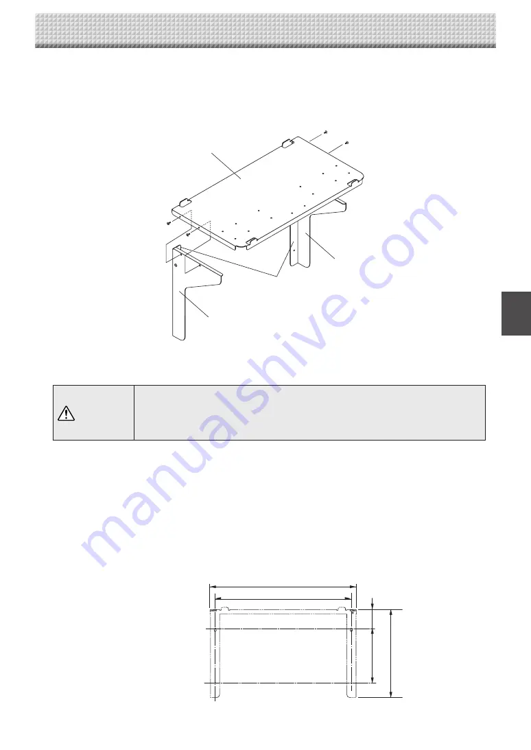
.  Assembling the printer table


 Fasten the brackets on the sides of the printer table using M4 x 8 screws (three each).


- There is one bracket for the left side, one for the right. Place the flange on the inner side.

6

.  Mounting the printer table on the wall surface

(1)  Preparing the place of mounting

CAUTION

•  Install the printer table so that the cable for connection with the main unit is within 

reach. 

•  Use a printer fitting within the maximum printer outer dimensions of 502 (width) x 275 

(depth) (including power cord and other connection cords, etc.). Use a printer weighing 
no more than 5 kg.

Place the wall printer table at the position in which it is to be mounted, then insert a gimlet or other pointed object 

accurately through the center of the screw holes to mark the wall surface.

• When the wall structure consists of plywood, etc.

  For panel walls, plaster board walls, etc., make sure there are columns or studs at the mounting dimension positions. 

If there are no columns at the desired installation position, mount a side board between nearby columns.

• For concrete walls

  Place commercially available anchor bolts and anchor nuts for M5 screws in the mounting positions.


Wall Mounting Dimensional Diagram

5. Wall Mounting 

78.6

173

302 (Printer table height)

460.6

502 (Printer table width)

M4x8
screws (2)

Left bracket

Flange

Printer table

Right bracket

M4x8 screws (2)

Содержание N-20 Series

Страница 1: ...N 20 N 20 Series Copyboard Assembly and Setup Manual English...

Страница 2: ...ssembly of the stand E 5 5 Wall Mounting E 8 6 Connecting the Cables With the Main Unit Connections Diagram E 14 7 Test Print E 15 To the Customer Special skills are required to install the set Never...

Страница 3: ...post in the wall or a sturdy wall stud When the mounting positions of the main unit are not reached please use optional wall support fittings Please use hardware like anchor nuts and anchor bolts for...

Страница 4: ...h power cord Dedicated markers 4 One each of black red blue and green Dedicated eraser 1 with 2 spare sponges USB cable 1 User s manual 1 Assembly and Setup Manual this manual 1 Important Safety Infor...

Страница 5: ...tray s screw holes and slide downwards as such to slip the pen tray into place Tighten the screws The method of installation differs according to the installation type When installed on the stand 4 As...

Страница 6: ...rew and Plain washer into the sleeve then use the hexagonal wrench to partially fasten it to the side bar Check that the sleeve is not sticking out Once mounting of the left and right T shaped feet is...

Страница 7: ...ily injury or damage the machine Alignment of the screw holes of the T shape feet with those of the stabilizers Slide the stabilizers on the T shaped feet to align with the holes CAUTION Do not lift t...

Страница 8: ...Do not bundle the cables together Doing so could cause them to heat up leading to fire Fasten the cables with the cable clip then insert them in the cable cover Put the cables into the AC adapter box...

Страница 9: ...ter of the bottom fixing bracket threaded hole Center of the top fixing bracket threaded hole standard type 1480 unit shape wide type 1980 unit shape 27 27 995 unit shape 70 70 Side board ex Stud Colu...

Страница 10: ...teel wall is reinforced and use a drill a hole of suit able diameter then attach the main unit with tapping screws Reference Installation Method for Various Wall Materials Please perform an installati...

Страница 11: ...ON Insert the unit in the top wall brackets with at least 2 people If the unit comes out of place it may fall and cause injury After mounting the unit in the top wall brackets hold the top of the unit...

Страница 12: ...e than 5 kg Place the wall printer table at the position in which it is to be mounted then insert a gimlet or other pointed object accurately through the center of the screw holes to mark the wall sur...

Страница 13: ...USB cable There is a cable hole on the wall side of the printer table Pass the DC cable of the main unit s AC power adapter and the printer s AC power cable through the printer table s cable hole bef...

Страница 14: ...not bundle the cables together Doing so could cause them to heat up leading to fire Put the cables in the notches top and bottom on the left side of the AC power adapter box and attach the AC power a...

Страница 15: ...lled on the stand See page E 5 When installed on a wall See page E 8 Main unit front To DC INPUT connector To DC connector To Printer connector To USB connector Printer USB cable supplied with the pri...

Страница 16: ...er 4 Open the top cover and open the paper tray 5 Set A4 or letter size paper 6 Write or draw a diagram on the sheet surface 7 Press the color print button for a color print the black and white print...

Страница 17: ...26 4607 11B...

Отзывы: