background image

175

RS-232C Adjustment

5.5.4 ID Assignment

After connecting to the PC, an ID is assigned.  The ID is assigned from the PC.

Commands:

<IDC> (ID CLEAR) ........ Clears the assigned ID

<IDS> (ID SET) ............. Assigns an ID

IDS is only effective when an ID is not assigned.

Also, IDs are set starting from the set closest to the PC.

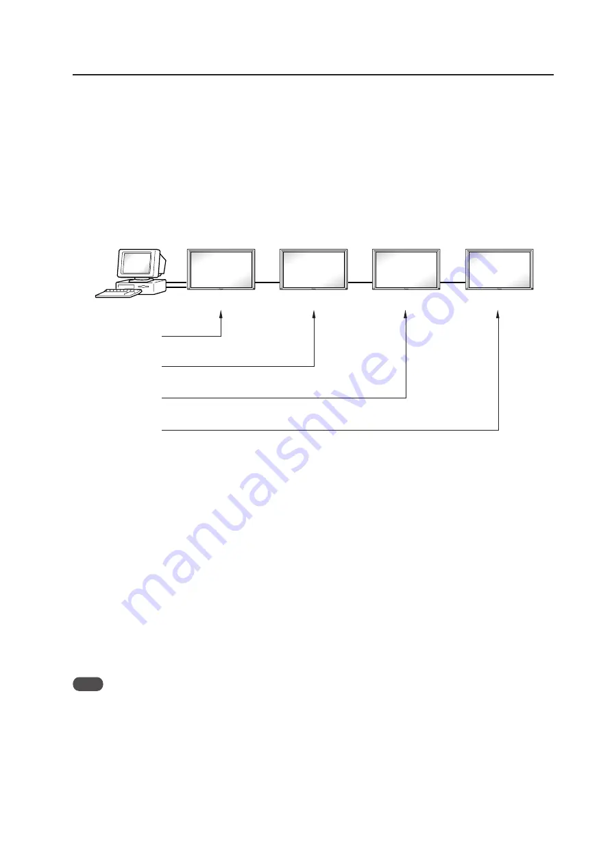
Example: Case of 4 displays (Assigning IDs with the PC for the first time)

First, as shown in the example in the figure below, perform an RS-232C connection and combination connection.

(Refer to section 5.5.3, “Combination Connection (pg. 174)”.)

By sending RS-232C commands in this order, it is possible to assign an ID for each set.

Sets for which an ID has been set can only receive commands with an ID attached. Attach an ID before sending a

command.

Characters that can be used for assigning an ID include, 0 - 9 and A - F (there is not distinction between upper case and

lower case alphabet characters).

An 

 (asterisk) can be used as follows:

<

∗∗

IDC>:  Clear the IDs assigned for all sets.

<2

IN1>: The input of only a set for which the first digit is 2 is set to INPUT1.

Precautions when assigning IDs

Sets that were connected after a set whose ID was cleared cannot be operated with RS-232C commands.

After performing setting as shown in the figure above, when <

∗∗

IDC> is performed, the IDs for all the sets from Set #1

to Set #4 are cleared, and only the one set (Set #1) that is directly connected to the PC can be controlled.

Furthermore, by performing <01 IDS>, it becomes possible to control the second set (Set #2). By setting IDs in the

same way for the other sets, it becomes possible to control the sets connected in succession.

Note

When the IDs are set, and when one or both of the IDs before a command is sent from the PC is 

, there is no echo

back. When sending more commands, wait 6 seconds before sending the next command.

Example)

When 

∗∗

OOO and 

1OOO or 1

OOO (OOO is the command) are sent from the PC, operation is performed,

but there is no echo back.

Set #4

ID = 04

Set #1

Set #2

Set #3

ID = 01

Sent commands:

1

<01 IDS>

2

<02 IDS>

3

<03 IDS>

4

<04 IDS>

ID = 02

ID = 03

PC

OUT

IN

OUT

IN

OUT

IN

±

RS-232C connection

Содержание PDP-42MXE10

Страница 1: ...sibility for losses resulting from the use of parts other than those supplied by us We guarantee the performance of our products only when they are assembled and adjusted as described in this manual The specifications and external designs shown in this manual are subject to change without notice CAUTION Exclamation marks placed within triangles are intended to alert users to the presence of import...

Страница 2: ...play 66 4 6 4 Angle setup 69 4 6 5 Measure to prevent shakiness when the unit is installed at a slight inclination 70 4 7 Wall Mount Unit PDK WM01 72 4 7 1 Specifications 72 4 7 2 External Dimensions 73 4 7 3 Assembling the mounting hardware and mounting the display 74 4 7 4 When removing the plasma display 76 4 8 Plasma Display Ceiling Mounting Hardware PDK 5012 78 4 8 1 Specifications 78 4 8 2 E...

Страница 3: ...le of Integrator Mode Operation 135 5 4 3 Adjustment and Setting in the Integrator Mode 136 1 PICTURE Adjustment 136 2 WHITE BALANCE Adjustment 137 3 COLOR DETAIL setting 138 4 GAMMA Setting 139 5 SCREEN Screen Position Adjustment 140 6 Brightness Enhancement BRT ENHANCE Setting at the Center of the Screen 141 7 SUB VOLUME Setting 142 8 Program Timer Setting 144 9 SCREEN MASK Setting 145 10 SIDE M...

Страница 4: ...devices other than PCs INPUT 2 Input Digital video signal HDCP supported INPUT 3 Input Y C separate video signal INPUT 4 Input Composite video signal Output Composite video signal INPUT 3 Input Audio L R signal INPUT 4 INPUT 5 Input Composite video signal RGB signals from AV devices or PCs Audio L R signal 7 PDA 5004 INPUT 1 Input Component video signal RGB signals from AV devices other than PCs I...

Страница 5: ...oducing a large 42 screen image the display is only 98 mm thick and weighs in at only 30 5 kg On the other hand the efficient heat radiating design greatly improves environmental operating conditions The thinner lighter design coupled to high endurance construction greatly broadens the range of possible installation locations and styles High reliability for commercial applications This display is ...

Страница 6: ...tching G ON SYNC 1 Vp p 75Ω negative sync Component video signal Y 1 Vp p 75 Ω negative sync PB CB PR CR 0 7 Vp p color 100 75 Ω Specifications PDA 5004 applies only when equipped with PDA 5004 INPUT 1 Input The following signal is supported only when a PDA 5004 is mounted Component video signal Y 1 Vp p 75 Ω negative sync PB CB PR CR 0 7 Vp p color 100 75 Ω INPUT 2 Input DVI D 24 pin connector Di...

Страница 7: ...tations when in original package Temperature 30 C to 60 C 22 F to 140 F Humidity 20 to 90 Atmospheric pressure 670 hPa to 1500 hPa Stacking Fewer than three tiers Standard accessories PDP 425CMX PDP 42MXE10 Power cord 1 Ferrite core for power cord 2 Ferrite core for audio cables 3 Cable tie 2 Remote control unit 1 AA battery 2 Wiping cloth for screen 1 Speed clamp 5 Operating instructions 1 Warran...

Страница 8: ...Hz 75 Hz 85 Hz 60 Hz 60 Hz 65 Hz 70 Hz 75 Hz 85 Hz 60 Hz 60 Hz 640x400 720x400 640x480 848x480 852x480 800x600 832x624 1360x765 1024x768 1280x768 1360x768 1376x768 1280x800 1280x854 1152x864 1152x870 1152x900 1440x900 1280x960 1280x1024 1400x1050 1680x1050 1600x1200 1920x1200 1920x1200RB NEC PC 9800 NEC PC 9800 Apple Macintosh 13 I O DATA I O DATA I O DATA I O DATA I O DATA Apple Macintosh 16 Work...

Страница 9: ... 800x600 1024x768 1280x768 1280x800 1280x854 1360x768 1376x768 1152x864 1152x900 1440x900 1280x960 1280x1024 1400x1050 1680x1050 1600x1200 1920x1200RB Work station SGI I O DATA I O DATA Work station SUN Work station SUN Apple Macintosh17 Work station SGI Work station EWS4800 Work station EWS4800 Work station HP Work station SUN CVT 31 5kHz 37 9kHz 37 5kHz 43 3kHz 51 1kHz 61 3kHz 31 0kHz 31 7kHz 35...

Страница 10: ...er to 3 3 2 Unpacking pg 24 Unit mm External Dimensions 952 1022 610 538 468 6 18 40 4 98 304 13 5 15 13 5 19 14 7 22 3 SPEAKER TERMINAL POWER BUTTON CONTROL BUTTONS AC INLET for PC 4 M4 DEPTH 10 BOTTOM VIEW RIGHT SIDE VIEW TOP VIEW LEFT SIDE VIEW REAR VIEW 921 6 SCREEN AREA 50 2 515 33 SCREEN AREA 47 34 1055 89 for mount unit 6 M8 DEPTH 18 for mount unit 8 M4 DEPTH 16 445 102 22 150 150 126 130 1...

Страница 11: ...h drawing PDP 425CMX PDP 42MXE10 connection panel when equipped with PDA 5004 Symbol indicating case of alignment with drawing 30 3 109 98 ø15 2 ø2 ø6 10 5 7 5 24 4 42 4 14 5 Indicator Ambient light sensor Light sensor for the remote 121 17 44 5 122 6 1212 28 38 42 33 37 37 18 21 5 14 22 18 18 18 18 36 5 14 132 6 62 5 43 78 8 121 17 44 5 122 6 1212 28 38 42 33 39 39 14 26 14 26 14 26 14 14 34 14 1...

Страница 12: ...ating When the unit is in standby mode The indicator lights red When flashing the indicator is used to indicate error messages 5 Handles Operation panel on the main unit 6 STANDBY ON button Press to put the display in operation or standby mode 7 MENU button Press to open and close the on screen menu 8 DISPLAY SET button Use to confirm onscreen menu selections and to change settings When not indica...

Страница 13: ...MAIN POWER switch is set to OFF or ON standby 4 AUDIO INPUT1 Stereo mini jack Use to obtain sound when INPUT1 is selected Connect this jack to the audio output connector of the device connected to the Plasma Display s INPUT1 5 AUDIO INPUT2 Stereo mini jack Use to obtain sound when INPUT2 is selected Connect this jack to the audio output connector of the device connected to the Plasma Display s INP...

Страница 14: ...or connection of an external left speaker Connect a speaker that has an impedance of 6 W AC IN A power cable is furnished with the Plasma Display connect one end of the power cable to this connector and the other end to a standard AC power source MAIN POWER switch Use to switch the main power of the Plasma Display on and off Video Card PDA 5003 Section The video card is provided with 3 video input...

Страница 15: ...n layout Pin No Input Output 1 R 2 G 3 B 4 NC not connected 5 GND 6 GND 7 GND 8 GND 9 DDC 5V NC not connected 10 GND 11 NC not connected 12 DDC SDA NC not connected 13 HD or H V SYNC 14 VD 15 DDC SCL NC not connected INPUT2 DVI D 24 pin connector female pin layout Signal Assignment 1 2 3 4 5 6 7 8 9 10 11 12 13 14 15 16 17 18 19 20 21 22 23 24 T M D S Data2 T M D S Data2 T M D S Data2 4 Shield NC ...

Страница 16: ...ss to video wall 0 AUTO SET UP button When using computer signal input automatically sets the POSITION CLOCK and PHASE to optimum values STANDBY ON button Press to put the unit in operation or standby mode DISPLAY button Press to view the unit s current input and setup mode POINT ZOOM button Use to select and enlarge one part of the screen FREEZE button When memo screen function is enabled a still...

Страница 17: ...he rear of the main unit or some other fixed surface so that it will be available for putting away the remote control unit when it is not in use Do not obstruct the ventilation holes in the remote control unit holder Example of remote control unit holder attachment Area of remote control unit holder attachment Remote control unit holder Remote control unit Upper and lower tape Caution ...

Страница 18: ...ent space for installation work The installation work should be conducted by two or more persons 5 Nearby equipment If air conditioning ducts or lamps etc are located near the installation site the attendant dust extreme temperatures humidity and condensation may become sources of trouble Please take sufficient steps to avoid this 6 Safe locations Do not install the unit where it may be easily tou...

Страница 19: ...lowing to allow a margin for power consumption per unit 320 W 320 VA NOTE The in rush current upon powering will be approximately 30 A A grounded three core power cable is used by the plasma display in order to maintain its functions Connect the power cord by inserting it in a grounded electrical outlet making sure that the cord is properly grounded When using a power source use conversion plug in...

Страница 20: ...wo fans and part A in a normal installation case draw off hot air from the unit All openings not assisted by fans serve as air inlets If the unit is hung from or embedded into a wall special operating temperature limits and other limitations may apply Refer to 3 4 Special Installation pg 28 414 5 374 5 372 4 137 3 81 3 137 3 81 3 52 6 149 8 98 8 114 5 52 6 39 8 98 8 114 5 264 5 43 1 24 8 127 7 74 ...

Страница 21: ...s are shown below Installation Conditions Always use a minimum of 4 mounting holes evenly distributed on opposite sides of both the horizontal and vertical center lines Use bolts that can be driven 12 mm to 18 mm into holes a and from 12 mm to 14 mm into holes b as shown in the Side View above Do not block or cover air outlets and openings for ventilation on the rear panel Take precautions to prev...

Страница 22: ...er lines as shown in the illustration below Do not secure the unit at four points in the manners shown below Methods for securing Unfavorable examples Methods for securing Favorable examples Secured at six points Secured at four points Secured at four points with mounting hardware attached to the sides XXXXXXXXXX Take proper precautions to prevent pinching the power cord or signal cables Secured a...

Страница 23: ...he illustration below diagonally extend string of maximum φ 0 1 mm diameter through the bolt mount openings Strings thus arranged should be completely free of slack 2 Measure the clearance L between the strings at their point of intersection Distortion is expressed by Distortion L 2 3 If L is found to be 0 pass the strings through the other bolt mount openings and repeat the measurements Any value...

Страница 24: ...de of glass Please take precautions to prevent it from being damaged 3 3 2 Unpacking The original packing material can be re used to sofely ship the Plasma Display When doing so it is important to use the material in the same way as when they were originally shipped Failure to correctly use the material can damage the display 1 Packing specifications 1177 mm W 767 mm H 354 mm D 38 kg 1 Upper Carto...

Страница 25: ...an up following unpacking are complete When moving the display it should always be carried by two persons holding the rear handles in the manner shown No Never attempt to move the plasma display by holding only one of the handles 3 3 3 Mounting on the attachment stands See 4 3 Installation of the Attachment Stand pg 50 for instructions on permanent installation Insert the stand bolts into A and A ...

Страница 26: ...ons on how to connect a PC or a audio device 2 Important notes Use coaxial cables As a rough guide for video signals use 3C 2V cables for lengths up to 15 meters and 5C 2V cables for lengths up to 30 meters Use thicker cables for computer signals since these signals are more likely to degrade 5C 2V cables for example for 15 meter lengths Generally thicker cables will produce more reliable connecti...

Страница 27: ... then snap 2 into the back of 1 to fix the clamp Speed clamps are designed to be difficult to undo once in place Please attach carefully To attach the speed clamps to the main unit Use the holes marked with the sign as needed To remove speed clamps Using pliers twist the clamp 90 and pull it outward In some cases the clamp may have deteriorated over time and may be damaged when removed As viewed f...

Страница 28: ...ittings should have a thickness of less than 20 mm This limit does not apply to fittings in examples 1 3 5 and 6 on the following page 5 L shaped fittings should have a thickness of less than 100 mm 6 The strength of the fittings should be adequate to bear the weight of the display 7 Take precautions to avoid sharply bending the power cable 8 If necessary it is possible to remove the handles When ...

Страница 29: ...ess Attach so that the fan is on the left side viewed from the rear Example 1 Example 2 Example 3 35 mm or less Example 4 Example 5 35 mm or less Example 6 35 mm or less Vertical installation Standard installation In cases where top and bottom are reversed ...

Страница 30: ...e distance between the unit and the wall the unit must be installed in such a way as to ensure free air flow With no obstructions within a distance of 300 mm from the unit Distance from wall A B C D Ambient temperature 50 mm or more 300 mm or more 300 mm or more 300 mm or more 0 C to 35 C Requirements when used with PDP S44 LR speaker system When installed as a single unit all requirements are the...

Страница 31: ...Free air flow With no obstructions within a distance of 300 mm from the unit Temperature of 0 C to 35 C Flush wall installation distance between unit and wall less than 50 mm 300 mm or more 100 mm or more 50 mm or more Panting net 300 mm or more 50 mm or more 50 mm or more Requirements Free air flow With no obstructions within a distance of 300 mm from the unit around all four sides of the unit is...

Страница 32: ...re trying to embed the unit in a wall and make sure to observe all the limitations specified below Be sure to mount the unit so that twisting bending or other deformation of the unit does not exceed 4 mm 1 Embedding in walls with space provided behind the unit With no obstructions within a distance of 300 mm from the back surface of the unit A Methods of Securing Basic methods of securing are show...

Страница 33: ...erence purposes Make measurements at a distance of 50 mm from the unit without directly subjecting the thermometer to fan exhaust For spaces where temperature fluctuations are likely gather additional measurement points for an adequate data set 50 mm 50 mm Thermometer temperature measurement point ...

Страница 34: ...Embedding in the wall 2 Embedding in walls with no space provided behind the unit Panting Punching net numerical aperture 50 or over 100 mm or more 100 mm or more 100 mm or more 100 mm or more 50 mm or more Methods of Securing Basic methods of securing are shown below Avoid blocking or covering areas aside from those indicated by The methods indicated by a large X mark must not be used Before atta...

Страница 35: ...an the following temperature range If hot air remains in the closed space the temperature may rise causing a malfunction or fire As a precaution in case of accidents the inner wall should have sufficient heat resistance or fire resistance Usage temperature conditions BOX air temperature Ambient temperature 0 C to 35 C Rear view the following area should be made of mesh A 50 B 50 C 10 D 50 A 50 mm ...

Страница 36: ...alling the plasma display do not use the handles as means of hanging the display 3 4 5 Ceiling suspension with wires When suspending from ceilings with wire attach the unit either at rows A and B or at rows C and D to keep it from deforming forces In addition the unit must be attached at four or more points with these points distributed symmetrically on opposite sides of the vertical and horizonta...

Страница 37: ...e methods indicated by a large X mark must not be used Before attaching the unit to fittings double check that the thickness and height of the fittings and the number of fixing bolts is correct Also refer to 3 4 1 Mounting to fittings pg 28 Vertical suspension Attach so that the fan is on the left side viewed from the rear Installation is not possible Installation is not possible ...

Страница 38: ...ollowing before attempting to mount the unit on the wall and observe the various limitations specified below Be sure to mount the unit so that twisting bending or any other deformation does not exceed 4 mm Shaded areas indicate attachment points for mounting hardware Operating Temperature Restrictions Distance from wall A B C D Ambient temperature 50 mm or more 100 mm or more 50 mm or more 50 mm o...

Страница 39: ...ickness and height of the fittings and the number of fixing bolts is correct Also refer to 3 4 1 Mounting to fittings pg 28 Heated air is drawn off from the interior of the unit by fans Before installation consider the heat resistance of the wall or other surfaces behind the unit Exhaust temperatures can be 30 C higher than the outside temperature For wall mounting do not bundle the cables in a wa...

Страница 40: ... unit 3 4 7 Place product upright and flush into wall embedding in the wall Carefully read the following before trying to embed the unit in a wall and make sure to observe all the limitations specified below Be sure to mount the unit so that twisting bending or other deformation of the unit does not exceed 4 mm 1 Embedding in walls with space provided behind the unit with no obstructions within a ...

Страница 41: ... from those indicated by The methods indicated by a large X mark must not be used Before attaching the unit to fittings double check that the thickness and height of the fittings and the number of fixing bolts is correct Also refer to 3 4 1 Mounting to fittings pg 28 Attach so that the fan is on the left side viewed from the rear Installation is not possible Installation is not possible ...

Страница 42: ...ient temperature 0 C to 35 C Special Installation Place product upright and flush into wall embedding in the wall 2 Embedding in walls with no space provided behind the unit Panting Punching net numerical aperture 50 or over 100 mm or more 100 mm or more 100 mm or more 100 mm or more 50 mm or more Attach this fan on the left side ...

Страница 43: ... from those indicated by The methods indicated by a large X mark must not be used Before attaching the unit to fittings double check that the thickness and height of the fittings and the number of fixing bolts is correct Also refer to 3 4 1 Mounting to fittings pg 28 Attach so that the fan is on the left side viewed from the rear Installation is not possible Installation is not possible ...

Страница 44: ...al surface 50 mm or more Methods of Securing Basic methods of securing are shown below Avoid blocking or covering areas aside from those indicated by The methods indicated by a large X mark must not be used Before attaching the unit to fittings double check that the thickness and height of the fittings and the number of fixing bolts is correct Also refer to 3 4 1 Mounting to fittings pg 28 Special...

Страница 45: ...lass etc on the front of the plasma display Usage temperature conditions Ambient temperature 0 C to 35 C Outside air temperature Space enclosed by the back surface of the plasma display 0 C to 35 C Use a fan etc to discharge air to maintain this temperature range Special installation Installed facing upward 10 mm 150 mm 50 mm A Outside air temperature measuring point Outside air temperature measur...

Страница 46: ...onnections While the display is designed to accommodate side by side installations keep in mind that specific installation configurations may affect ventilation Observe the following requirements 1 Installation of up to two units Horizontal connection The following table lists the operating temperature conditions Use the units under conditions that keep the outside atmosphere in this range Special...

Страница 47: ...rature conditions Use the units under conditions that keep the outside atmosphere in this range Special installation Multiple A Unit A Unit B Unit B Partition In case of lateral connections ensure that left and right partitions are provided Be careful to install the partitions so that the air on the left and right backside of the set is not mixed up Operating Temperature Restrictions Distance from...

Страница 48: ...bles vertical placement of the unit Tilt Mount Unit PDK 5011 Permits tilting of the display downward from the horizontal by up to 25 degrees Mount depth is 143 mm or less in vertical position without optional speaker This hardware permits a wide range of viewing angles Wall Mount Unit PDK WM01 Distance from the rear surface of the plasma display to the wall is 32 mm It is provided with many instal...

Страница 49: ...Even if the particulars of an installation are letter perfect your work may be perceived as inadequate unless you patiently and thoroughly explain these precautions so that the customer fully understands them The following are highly dangerous and must be avoided at all times Any sudden application of force including pushing and pulling Splashing water on the unit Placing any object on the unit To...

Страница 50: ...f the 4 prepared holes using commercially available M8 bolts 2 Insert the unit into the stand 3 Tighten the bolt against the washer so as to secure the unit The unit weights 30 kg or more and its thinness makes it unstable Therefore it should be unpacked carried and installed by two or more persons CAUTION Front Rear 110 mm Use a 6 mm hexagonal wrench to tighten the bolt Always install the supplie...

Страница 51: ...51 Installation of the Attachment Stand Dimensions Unit mm 23 610 633 447 2 70 1022 40 4 74 3 98 127 7 300 252 4 31 4 22 1 10 79 10 53 5 24 3 10 12 50 110 66 8 ø24 R12 70 300 ...

Страница 52: ... C separate video signal Y 1 Vp p 75 Ω negative sync C 0 285 Vp p 75 Ω NTSC 0 3 Vp p 75 Ω PAL INPUT4 Input BNC jack Composite video signal 1 Vp p 75 Ω negative sync Output BNC jack 75 Ω with buffer INPUT5 Input BNC jack 5 RGB signal for G ON SYNC RGB 0 7 Vp p 75 Ω no sync HD VS VD TTL level positive and negative polarity 75 Ω or 2 2 kΩ with impedance switching G ON SYNC 1 Vp p 75 Ω negative sync C...

Страница 53: ...G ON SYNC G ON SYNC 1 Vp p 75 Ω negative sync RGB 0 7 Vp p 75 Ω no sync Component video signal Y 1 Vp p 75 Ω negative sync PB CB PR CR 0 7 Vp p color 100 75 Ω Audio related Input AUDIO INPUT for INPUT3 Pin jack 2 L R 500 mVrms more than 10 kΩ AUDIO INPUT for INPUT4 Pin jack 2 L R 500 mVrms more than 10 kΩ AUDIO INPUT for INPUT5 Pin jack 2 L R 500 mVrms more than 10 kΩ Accessories Label for remote ...

Страница 54: ...54 4 4 2 External Dimensions Unit mm 7 PDA 5003 Video Card PDA 5003 PDA 5004 148 9 137 3 301 5 27 6 262 7 PDA 5004 137 3 148 3 27 6 301 5 262 ...

Страница 55: ...y Before installation take precautions to eliminate static electricity on your body Do not touch the card s circuitry or devices This device has not been designed to allow reinstallation or removal after the card has once been installed on the plasma display do not attempt to remove it since damage may result When installing the PDA 5003 it may be necessary to adjust the setting of the impedance s...

Страница 56: ...ould not be attempted 1 Remove the two screws holding the video card AUDIO INPUT5 INPUT 3 4 AUDIO VIDEO ANALOG RGB HD H V SYNC S VIDEO INPUT3 INPUT4 2 Holding the inside tabs pull the video card out straight AUDIO INPUT5 INPUT 3 4 AUDIO VIDEO ANALOG RGB HD H V SYNC S VIDEO INPUT3 INPUT4 Impedance selector switch 75 Ω 2 2 kΩ Device mounting surface AUDIO INPUT5 INPUT 3 4 AUDIO VIDEO ANALOG RGB HD H...

Страница 57: ...57 Video Card PDA 5003 PDA 5004 ...

Страница 58: ...ons 640 mm W 214 mm H 415 mm D 25 3 16 in W 8 7 16 in H 16 11 32 in D Package weight 6 3 kg 13 9 lbs Accessories Base cover 1 Stand pipes left and right interchangeable 2 Screw 4 8 4 Installation bolt 1 M8 20 2 Installation bolt 2 M8 40 2 Hexagonal wrench 1 Stabilization bolts 2 Operating instructions 1 Table Top Stand PDK TS01 Operating Temperature Restrictions Ambient Temperature 0 C to 40 C Ope...

Страница 59: ...the stand to the floor When stabilizing the stand to the floor use M6 with a length above 20 mm Unit mm Table Top Stand PDK TS01 4 5 3 External Dimensions 7 When using plasma display Unit mm 610 150 220 339 508 566 1022 64 275 248 388 566 11 5 R6400 R4200 R6400 550 ...

Страница 60: ...top screwing down the bolt when the threads are no longer visible Holes a Plasma display housing 4 5 5 Stand attaching to the Plasma Display 1 Normal Installation 1 With the plasma display lying flat insert and secure the two Installation bolts 1 M8 20 in the holes a located in the plasma display housing At this point tighten these bolts 1 only until the threads are no longer visible when viewed f...

Страница 61: ...ssemble only with the plasma display lying flat on a table or similar surface 3 Do not apply excessive pressure and tighten the bolts more than necessary 4 Move the stand so that the stand screw holes and the nuts that connect the main display line up correctly 5 The display weighs approximately 30 kg 66 lbs or more and has little depth making the display very unstable For this reason at least two...

Страница 62: ...d Plasma display Mirror mat Pads Inner box frame Plasma display Mirror mat Inner box frame topped by two pads Pad 1 Construct the stand for the plasma display using the inner box frame and pads shown in the figure above 2 Set the plasma display down on the pads as shown in the figure below 3 Follow the instructions in Steps 1 4 in Normal Installation to attach the stand to the plasma display ...

Страница 63: ...play 2 Stabilize the display by connecting to a wall or standing beam with a strong cord Repeat the same steps in the laterally direction to stabilize the assembly to the left and right Use cord and hooks that are available on the market sold separately 7 How to use the stabilization bolts 7 Stabilizing to the floor Use screws sold separately to attach and stabilize the stand 1 2 ...

Страница 64: ...aging 890 W 120 H 700 D mm 35 1 8 W 4 23 32 H 27 9 16 D in Package weight 18 0 kg 39 7 lbs Layers of packing 20 layers Components Hung on wall unit 1 Bolt M8 6 Hexagonal wrench 1 In wall mounting installation allow adequate space a clearance of 300 mm or more above and below the monitor set as well as on the right and the left Operating Temperature Restrictions Ambient temperature 0 C to 40 C Oper...

Страница 65: ...65 Tilt Mount Unit PDK 5011 4 6 2 External Dimensions 7 When using plasma display Units mm 236 47 8 0 05 32 98 455 555 655 496 1022 212 410 232 465 545 8 73 150 150 35 35 35 610 25 740 573 45 143 ...

Страница 66: ...a horizontal position in front of the screen In this case you can hide the top of the screw by using the holes without a red triangle mark Wall side hardware PDP side hardware PDP side hardware Top side of plasma display 1 Remove the special screws 2 locations from the bot tom of the hung on wall unit Top side of plasma display Note Be sure to install the speaker at this stage For the installation...

Страница 67: ...he front In this case you can hide the top of the screw by using the hole towards the top not marked with a red For details see 4 6 4 Adjusting the Angle pg 69 Top side of plasma display Notes If you plan to install speakers and cables please install them at this stage Do not connect the cables to the other device For the speaker installation method refer to the speaker installation procedure in t...

Страница 68: ...tallation hardware on the speaker and using the screws that come with the speaker anchor both from the bottom 2 locations on the left and right Note Be sure to install the speaker with the hardware attached vertically 7 Fix the bottom of the hardware with the special screws removed at step 1 one on the left and one on the right Special screw M6 ...

Страница 69: ...e vertical to 25 This adjustment must always be done by 2 people Adjust the angle by rotating the screws at the center top and center bottom of the wall side hardware to the left or right Notes If the angle is increased while you are adjusting the angle using the screw at the center of the bottom it is difficult to turn the screw When this happens adjust it at the center of the upper Turn the scre...

Страница 70: ... to loosen left right the installation screws on the resin plate used as a guideline when installing it vertically left right so that the resin plate can move freely 2 Slide the resin plate left right forward along the slit to the rear cover of the plasma display 3 If when it is moved only forward the distance is too short rotate the resin plate to use the long side direction 4 After setting the r...

Страница 71: ...71 Tilt Mount Unit PDK 5011 ...

Страница 72: ... wall unit 1 Tilt adjustment metal fitting 1 Bolt M8 6 Hexagonal wrench Opposite side 6 mm for M8 use 1 Stencil 1 In wall mounting installation allow adequate space a clearance of 300 mm or more above and below the monitor set as well as on the right and the left Operating Temperature Restrictions Ambient temperature 0 C to 40 C Operating Temperature Restrictions for Upside Down Installations Upsi...

Страница 73: ... 17 6 x 120 2 φ 6 0 64 97 388 30 30 396 32 27 197 197 98 455 540 910 145 27 135 135 45 45 682 5 940 120 150 150 425 120 496 225 41 41 Center line Center of the display 1022 610 4 7 2 External Dimensions 7 When using plasma display Unit mm ...

Страница 74: ... later 3 Removing the PDP side metal fitting 1 Lift the lock bar to the position where the lock on the PDP side metal fitting is released 2 While holding the lock bar up pull out the bottom of the PDP side metal fitting 3 Lift up and remove the PDP side metal fitting 1 1 3 2 Lock bar PDP side metal fitting PDP side metal fitting Bolts M8 Top side of the plasma display 4 Attaching the PDP side meta...

Страница 75: ...ing disappears When the gap between the wall side metal fitting and the tilt adjustment metal fitting has disappeared the screw becomes difficult to rotate and begins to lift up the plasma display 2 Rotate the screw to adjust the tilt Gap Screw head Tilt adjustment metal fitting Tilt adjustment metal fitting 5 Installing the wall side metal fitting on the wall Fix it firmly in place symmetrically ...

Страница 76: ...ocked position Locked position 4 7 4 When removing the plasma display Before beginning this procedure turn off the power to the plasma display and peripheral devices and remove their power plugs from the outlets As necessary also remove connecting cables 2 Removing the push rivet and the anchor screws that are holding the lock plate and the anchor screws that are holding the PDP metal fitting 2 lo...

Страница 77: ...the plasma display 5 Raising and removing the plasma display Raise and remove the plasma display Pull out the bottom of the plasma display very carefully so that the hook on the PDP side metal fitting is not displaced Always have at least 2 people do this task Raise the lock bar either the left or the right side Caution Caution ...

Страница 78: ... 4 W 14 3 16 H 21 1 4 D in Package weight 21 5 kg 51 8 lbs Layers of packing 10 layers Components PDP bracket 1 Bolt M8 6 Special screw 4 Hole cover 1 Stencil printed on the wrapping material that is inside 1 Installer s contact information Japan only 1 Operating instructions 1 The appropriate types of screws and other mounting hardware will depend on the strength and composition of the ceiling Pr...

Страница 79: ... 980 496 530 300 R580 R510 45 45 610 φ60 5 This circle shows the path that the outermost part of the plasma display follows when it is rotated about a vertical axis after having been titled sideways by 25 This circle shows the path that the outermost part of the plasma display follows when it is rotated about a vertical axis after having been titled sideways by 25 Attachment use holes 6 locations ...

Страница 80: ...xagonal wrench subtense 6 mm for M8 bolts You ll also need tools for ceiling work 2 Installing the mounting hardware Select the installation site then apply the supplied pattern to the ceiling drill the holes and mount the ceiling suspension hardware The appropriate types of screws and other display mounting hardware will depend on the strength and composition of the particular ceiling Firmly tigh...

Страница 81: ...it on top of a flat table or similar surface Be careful that the PDP bracket is not upside down 3 Attach the plasma display to the hanger 4 Screw the plasma display to the hanger at 4 locations PDP bracket Top side of plasma display Hanger Plasma display Top side of plasma display 2 Fix the plasma display to the PDP bracket with screws 6 locations Note Be sure to use the holes shown on 43 to attac...

Страница 82: ...ening the screws on the left and right sides You can adjust it a maximum of 25 downwards from the vertical position Set it to the desired angles while supporting the plasma display and retighten the loosened screws on the left and right sides The hole on the side indicates the angle 5 units Detailed Angle Standard Diagram Connecting cable when coming out of the top of the supporting column Connect...

Страница 83: ...83 Plasma Display Ceiling Mounting Hardware PDK 5012 ...

Страница 84: ...er metallic Dimensions of packaging 1465 mm W 200 mm H 790 mm D 57 7 8 in W 7 7 8 in H 31 3 32 in D bracket display stand section 810 mm W 295 mm H 810 mm D 31 7 8 in W 11 15 16 in H 31 7 8 in D stand shelf leg section Package weight 38 kg 83 8 lbs bracket display stand section 21 kg 46 3 lbs stand shelf leg section Layers of packing 10 layers Components Display stand 1 Rear cover 1 Leg base 1 Bra...

Страница 85: ...elf installed at the highest position 773 5 1350 Center of the display screen when it is installed at the upper position 1170 Center of the display screen when it is installed at the lower position 1518 5 1314 1070 1665 132 3 75 143 3 110 180 330 Stand shelf installed at the lowest position 5 Tilt angle 1 440 2 430 1 220 2 230 60 720 406 ø60 1 650 2 670 1 710 2 730 22 Note Dimensions 1 Compatible ...

Страница 86: ...o not take out the screws Back casters Display stand Leg base Hexagonal bored bolts M8 60 Washer Plate spring washer Support caster Label 4 9 4 How to install In order to ensure safety during installation always be sure to work together with more than two persons 1 Assemble the unit Attach the leg base to the display stand using the hexagonal bored bolts M8 60 so that the rear label faces towards ...

Страница 87: ...ket bolts may not be screwed into the third set of screw holes from the top as these screw holes are used in Step 4 below Display stand Hexagonal bored bolts M8 20 5 to 6 mm 3 Attaching bracket to plasma display Using the hexagonal bored bolts M8 20 attach the bracket to the rear of the plasma display by screwing the bolts into the screw holes as the figure Notes The plasma display should be place...

Страница 88: ...thstand load 20 kg Mobile Cart PDK 5014 5 0 Display stand Slits Hook Insert the hook securely into the slit Caution 4 Attaching a panel to the stand once the bracket has been attached 1 Fix the holes on the protruding portion of the bracket onto the left and right bolts attached to the display stand 2 Using two hexagonal bored bolts M8 x 20 fix the bracket to the left and right sides of the displa...

Страница 89: ...r touches the floor 2 Turn the nut at the top of the caster in the direction indicated by the arrow to fix the caster into place 7 Hang the cords on the hooks on the back of the support columns 8 Attach the rear cover Attach the rear cover and fix it in place by tightening the finger screws Be careful not to catch the cable in the rear cover Mobile Cart PDK 5014 Bottom of support caster Support ca...

Страница 90: ... 5 8 in H 12 17 32 in D Package weight 6 2 kg 10 1 lbs Cabinet Enclosed type antimagnetic design Used speakers two way method Woofer for low tones 8 cm cone type Tweeter for high tones 5 cm cone type Nominal impedance 6 Ω Frequency Range 70 Hz to 20 000 Hz Sensitivity 84 dB W at 1 m distance Permissible input Max input 30 W Rated input 10 W Crossover frequency 250 Hz Accessory parts for 2 speakers...

Страница 91: ...91 4 10 2 External Dimensions when mounted to the plasma display Units mm Speaker System PDP S44 LR These are the dimensions of the side surface of the speaker 90 1022 1204 54 18 33 7 33 7 94 4 610 ...

Страница 92: ...ma display the speaker may cause irregular color or other effects Should this occur please move the speaker away from the display 1 Attach the cushions to the sides of the speakers in the positions indicated on the diagram Cushions 2 Partially tighten the included screws M8 in the screw holes on the top of the display Screws M8 3 Catch the hooks on the top of the speakers to the partially tightene...

Страница 93: ...eutral detergent solution wring well and afer wiping remove moisture by wiping with a dry colth If you want to use a chemical cloth for cleaning read well the caution provided with the chemical cloth product Do not use solvent such as thinner or benzine for cleaning Otherwise the surface finish will be deteriorated or the coating will be stripped off To remove dust from the speaker nets use a brus...

Страница 94: ...ls by RS 232C commands Note 1 Refer to section 5 4 1 About the Integrator Mode pg 134 Note 2 Does not move unless POWER MANAGEMENT ON is set 1 Normal Operation Mode This mode is for playing video In this mode the following basic controls are performed Moving to the power standby state Switching the input Switching the screen Volume adjustment Mute the sound remote control only AUTO SET UP only whe...

Страница 95: ...s that can only be operated in this mode For details refer to section 5 5 RS 232C Adjustment pg 172 5 1 2 Combined Use of the Remote Control Main control Panel and Personal Computer The remote control and main control panel can be operated together Example It is possible to perform an operation such as designating the Menu Mode using the main control panel and then performing adjustment using the ...

Страница 96: ...080p HDTV 1250p HDTV 525i 480i SDTV 525p 480p SDTV 1125i 1080i HDTV 1125i 1035i HDTV 750p 720p HDTV 1125p 1080p HDTV Refresh rate WIDE 14 9 2 35 1 INPUT3 Signal Format S Video Y C S Video Y C S Video Y C S Video Y C S Video Y C S Video Y C 4 3 FULL ZOOM WIDE CINEMA 14 9 2 35 1 Remark Screen size NTSC PAL SECAM 4 43 NTSC PAL M PAL N 1 Can be selected from either FULL1080i or FULL1035i 2 Some visual...

Страница 97: ...852x480 800x600 832x624 1360x765 1024x768 1280x768 1360x768 1376x768 1280x800 1280x854 NEC PC 9800 NEC PC 9800 Apple Macintosh 13 I O DATA I O DATA I O DATA I O DATA I O DATA Apple Macintosh 16 Work station SGI indicates Apple Macintosh 19 I O DATA I O DATA I O DATA CVT PC 1024x768 1024x768 1024x768 1024x768 1024x768 1024x768 1024x768 1024x768 1024x768 1024x768 1024x768 1024x768 1024x768 1024x768 ...

Страница 98: ...z 71 7kHz 56 0kHz 60 0kHz 64 0kHz 64 6kHz 75 1kHz 78 1kHz 80 0kHz 81 1kHz 91 2kHz 108 5kHz 65 3kHz 82 3kHz 93 9kHz 65 3kHz 75 0kHz 81 3kHz 87 5kHz 93 8kHz 106 3kHz 74 6kHz 74 0kHz 768x768 768x768 768x768 768x768 720x768 768x768 768x768 1024x768 1024x768 1024x768 1024x768 1024x768 1024x768 1024x768 1024x768 1024x768 1024x768 1024x768 Apple Macintosh 21 Sun Microsystems LO Sun Microsystems HI Apple ...

Страница 99: ...0kHz 64 6kHz 75 1kHz 78 1kHz 81 1kHz 80 0kHz 91 2kHz 65 3kHz 65 3kHz 75 0kHz 74 0kHz 1024x768 768x768 768x768 768x768 768x768 768x768 768x768 720x768 768x768 1024x768 1024x768 1024x768 1024x768 1024x768 1024x768 1024x768 1024x768 1024x768 1024x768 1024x768 1024x768 1024x768 1024x768 1024x768 Work station SGI I O DATA I O DATA Work station SUN Work station SUN Apple Macintosh17 Work station SGI Wor...

Страница 100: ...l this is for a cinesco cinema scope size video 4 3 For a 4 3 source roundness can be accurately reproduced In order to prevent burning of the screen this screen size should not be used when possible DOT BY DOT The input signal corresponds 1 1 with the pixels of the plasma display for an accurate reproduction This screen size exists for a personal computer signal when the input signals a less than...

Страница 101: ...OFF DISABLE ENABLE DISABLE DNR OFF LOW MIDDLE HIGH MIDDLE MPEG NR OFF LOW MIDDLE HIGH LOW CTI OFF ON ON PURECINEMA OFF ON OFF COLOR DECODING RGB COMP 1 COMP 2 COMP 1 2 COLOR SYSTEM AUTO NTSC PAL SECAM 4 43NTSC PAL M PAL N AUTO SIGNAL FORMAT AUTO AUTO DVI SET UP PLUG PLAY PC VIDEO PC BLACK LEVEL LOW HIGH LOW OPTION NOTE 1 LANGUAGE ENGLISH FRANÇAIS ESPAÑOL DEUTSCH ITALIANO ENGLISH ENERGY SAVE AUTO M...

Страница 102: ...HIGH HIGH MIDDLE POWER MGT OFF ON OFF AUTO POWER OFF DISABLE ENABLE DISABLE DNR OFF LOW MIDDLE HIGH MIDDLE MPEG NR OFF LOW MIDDLE HIGH LOW CTI OFF ON ON PURECINEMA OFF ON OFF COLOR DECODING RGB COMP 1 COMP 2 COMP 1 2 COLOR SYSTEM AUTO NTSC PAL SECAM 4 43NTSC PAL M PAL N AUTO SIGNAL FORMAT AUTO AUTO OPTION NOTE 1 LANGUAGE ENGLISH FRANÇAIS ESPAÑOL DEUTSCH ITALIANO ENGLISH ENERGY SAVE AUTO MODE1 MODE...

Страница 103: ...ABLE DNR OFF LOW MIDDLE HIGH MIDDLE MPEG NR OFF LOW MIDDLE HIGH LOW CTI OFF ON ON PURECINEMA OFF ON OFF COLOR DECODING RGB COMP 1 COMP 2 COMP 1 2 COLOR SYSTEM AUTO NTSC PAL SECAM 4 43NTSC PAL M PAL N AUTO SIGNAL FORMAT AUTO AUTO DVI SET UP PLUG PLAY PC VIDEO PC BLACK LEVEL LOW HIGH LOW OPTION NOTE 1 LANGUAGE ENGLISH FRANÇAIS ESPAÑOL DEUTSCH ITALIANO ENGLISH ENERGY SAVE AUTO MODE1 MODE2 MODE3 STAND...

Страница 104: ...EN BLUE YELLOW OFF SIDE MASK R LEVEL 0 to 255 80 G LEVEL 0 to 255 80 B LEVEL 0 to 255 80 VIDEO WALL DIVIDER 1 4 9 16 25 OFF POSITION Refer to pg 147 Refer to pg 147 TYPE NORMAL ADJUSTED NORMAL AUTO ID ON OFF OFF P ON DELAY OFF ON MODE1 MODE2 OFF ABL LINK ON OFF OFF REPEAT TIMER Refer to pg 150 Refer to pg 150 BAUD RATE 9600BPS 19200BPS 38400BPS 1200BPS 2400BPS 4800BPS 9600BPS ID NO SET OIH FFH ALL...

Страница 105: ...g 144 Refer to pg 144 SCREEN MASK OFF INVERSE WHITE RED GREEN BLUE YELLOW OFF SIDE MASK R LEVEL 0 to 255 80 G LEVEL 0 to 255 80 B LEVEL 0 to 255 80 VIDEO WALL DIVIDER 1 4 9 16 25 OFF POSITION Refer to pg 147 Refer to pg 147 TYPE NORMAL ADJUSTED NORMAL AUTO ID ON OFF OFF P ON DELAY OFF ON MODE1 MODE2 OFF ABL LINK ON OFF OFF REPEAT TIMER Refer to pg 150 Refer to pg 150 BAUD RATE 9600BPS 19200BPS 384...

Страница 106: ...ITE RED GREEN BLUE YELLOW OFF SIDE MASK R LEVEL 0 to 255 80 G LEVEL 0 to 255 80 B LEVEL 0 to 255 80 VIDEO WALL DIVIDER 1 4 9 16 25 OFF POSITION Refer to pg 147 Refer to pg 147 TYPE NORMAL ADJUSTED NORMAL AUTO ID ON OFF OFF P ON DELAY OFF ON MODE1 MODE2 OFF ABL LINK ON OFF OFF REPEAT TIMER Refer to pg 150 Refer to pg 150 BAUD RATE 9600BPS 19200BPS 38400BPS 1200BPS 2400BPS 4800BPS 9600BPS ID NO SET ...

Страница 107: ...is designated by a remote control main control panel or POF command When an adjustment or setting is changed using a command When the format of the displayed signal changes Item Memory Timing Note In the case of a permanent installation when the entire system is started or stopped by turning ON OFF the breaker use the system only after first saving adjustments and settings in the last memory accor...

Страница 108: ... copyright of the creator according to copyright laws 2 Display call A Pressing the DISPLAY button on the remote control or main control panel will display the current input function horizontal and vertical frequency of the input signal the type of signal and screen size DISPLAY CALL 1 Note The horizontal and vertical frequencies that are displayed are measured values Measurement errors are possib...

Страница 109: ...ring magnification it is possible to scroll the display position using the 5 2 3 buttons on the remote control 7 Multi screen only when using the remote control Pressing the SPLIT button on the remote control designates a multi screen and each time the button is pressed the screen changes as shown below When input is switched during a multi screen display input of the main screen is switched When ...

Страница 110: ...Memory Area Tables pg 167 3 Precautions 1 In the following cases the menu mode is automatically released and operation mode returns to the normal operation mode When input is switched When there is no operation in about 3 minutes 2 For details about adjustment in the menu mode refer to the Operating Instructions 3 It is recommended that adjustment and settings be performed while the video signal t...

Страница 111: ...SCREEN SETUP OPTION 0 0 0 CONTRAST 0 BRIGHTNESS H ENHANCE V ENHANCE PICTURE RESET PICTURE MENU INPUT1 ENTER SET EXIT MENU 3 Use the 2 3 buttons to adjust the picture quality as desired 0 BRIGHTNESS SET SET EXIT MENU It is possible to move to other adjustment items with the 5 button 4 Press the SET button Pressing the SET button writes the value into the memory and returns the display to the step 2...

Страница 112: ...H Corresponds to 1000 k HIGH Corresponds to 2000 k Settable condition When there is video signal input Factory setting MIDDLE 1 Select SETUP 2 Place the cursor over COLOR TEMP and press the SET button 3 Each time the 2 3 buttons are pressed the setting changes as shown below Screen 2 MENU INPUT1 CHANGE SET EXIT MENU SCREEN SETUP OPTION PICTURE DISABLE MIDDLE COLOR TEMP MIDDLE AUTO POWER OFF DNR LO...

Страница 113: ...state to the normal operation state press the power button on the remote control or the main control panel To return from the energy saving state by power management to the normal operation state operate the personal computer or press the INPUT button on the remote control or main control panel However during G ON SYNC or composite SYNC input operation does not return by simply operating the perso...

Страница 114: ...nal Settable conditions When there is video signal input Factory setting MIDDLE 1 Select SETUP 2 Place the cursor over DNR and press the SET button 3 Each time the 2 3 buttons are pressed the setting changes as shown below Note XXXXXXXX MENU INPUT1 ENTER SET EXIT MENU SCREEN SETUP OPTION PICTURE DISABLE MIDDLE COLOR TEMP MIDDLE AUTO POWER OFF DNR LOW ON MPEG NR CTI OFF RGB PURECINEMA COLOR DECODIN...

Страница 115: ...ition When there is video signal input Factory setting LOW 1 Select SETUP 2 Place the cursor over MPEG NR and press the SET button 3 Each time the 2 3 buttons are pressed the setting changes as shown below MENU INPUT1 ENTER SET EXIT MENU SCREEN SETUP OPTION PICTURE DISABLE MIDDLE COLOR TEMP MIDDLE AUTO POWER OFF DNR LOW ON MPEG NR CTI OFF RGB PURECINEMA COLOR DECODING AUTO COLOR SYSTEM SIGNAL FORM...

Страница 116: ...re is video signal input Factory setting ON 1 Select SETUP 2 Place the cursor over CTI and press the SET button 3 Each time the 2 3 buttons are pressed the setting changes as shown below MENU INPUT1 ENTER SET EXIT MENU SCREEN SETUP OPTION PICTURE DISABLE MIDDLE COLOR TEMP MIDDLE AUTO POWER OFF DNR LOW ON MPEG NR CTI OFF RGB PURECINEMA COLOR DECODING AUTO COLOR SYSTEM SIGNAL FORMAT Screen 2 CTI ON ...

Страница 117: ...ut Factory setting OFF 1 Select SETUP 2 Place the cursor over PURECINEMA and press the SET button 3 Each time the 2 3 buttons are pressed the setting changes as shown below OFF I P conversion is performed without detecting the signal of the film source ON The signal of the film source is detected and I P conversion is performed The ADVANCED mode can only be used when the input signal is 60 Hz Note...

Страница 118: ...pes of display call signals 50 60 Component RGB Component RGB Component RGB Component RGB Component RGB Component RGB Component RGB Component RGB Component RGB Component RGB Component RGB PURECINEMA 625i 576i SDTV 1125i 1080i HDTV 625p 576p SDTV 750p 720p HDTV 1125p 1080p HDTV 1250p HDTV 525i 480i SDTV 525p 480p SDTV 1125i 1080i HDTV 1125i 1035i HDTV 750p 720p HDTV 1125p 1080p HDTV Refresh rate No...

Страница 119: ...ECAM signal input Set COLOR SYSTEM SECAM For 4 43NTSC signal input Set COLOR SYSTEM 4 43NTSC For PAL M signal input Set COLOR SYSTEM PAL M For PAL N signal input Set COLOR SYSTEM PAL N By fixing the settings when the input signal is already known in advanced it is possible to perform smooth image processing and to prevent mistaken signal determination Settable condition INPUT3 INPUT4 Factory setti...

Страница 120: ...It is distinguished as in 5 1 3 List of Input Correspondence Signals 2 Input correspondence signals personal computer signals pages 97 to 99 Others Selectable resolutions are displayed Note The display method and selectable screen size differs for each setting In order to obtain a proper reproduction method and screen size check the signal format setting when the signal is input and change the set...

Страница 121: ...T button is pressed the setting changes as shown below XXXXXXXXX 4 Place the cursor over BLACK LEVEL and press the SET button to change the setting Each time the SET button is pressed the setting changes as shown below Note XXXXXXXXXXXXX MENU INPUT1 SET EXIT MENU SCREEN SETUP OPTION POWER MGT OFF SIGNAL FORMAT PICTURE DVI SET UP ENTER Screen 2 Screen 3 3 PC VIDEO 2 CHANGE SET EXIT MENU DVI SET UP ...

Страница 122: ...1250p signal input COMPONENT2 1 Select SETUP 2 Place the cursor over COLOR DECODING and press the SET button to change the setting Each time the SET button is pressed the setting changes as shown below Set COLOR DECODING as follows Please take care when making settings Incorrect settings can adversely affect the Plasma Display MENU INPUT1 CHANGE SET EXIT MENU SCREEN SETUP OPTION DISABLE MIDDLE COL...

Страница 123: ...Each time the 2 3 buttons are pressed the language changes as shown below With the desired language displayed press the SET button Note When the screen display language setting is performed for either INPUT1 or INPUT2 INPUT1 to INPUT5 when a PDA 5003 PDA 5004 is mounted the same display language is set regardless of the input LANGUAGE ENGLISH SET SET EXIT MENU Screen 3 3 ENGLISH 2 3 ESPAÑOL 2 3 DE...

Страница 124: ...sumption and reduces deterioration of the panel by controlling the brightness of the screen according to the input signal To make the screen bright and easy to see Set ENERGY SAVE STANDARD To reduce power consumption Set ENERGY SAVE MODE1 MODE2 To reduce deterioration of the panel such as burning Set ENERGY SAVE MODE 3 To perform control according to the brightness of the room and to adjust the sc...

Страница 125: ...ressed the setting changes as shown below The ENERGY SAVE setting is common for all inputs MENU INPUT1 CHANGE SET EXIT MENU SCREEN SETUP OPTION LANGUAGE ENERGY SAVE TIMER SETTING SCREEN MGT SPLIT FREEZE AUTO SETUP MODE AUTO FUNCTION PIP DETECT PICTURE STANDARD INACTIVE OFF ACTIVE ENGLISH OFF Screen 2 3 STANDARD MODE2 2 MODE1 2 3 AUTO MODE3 2 ...

Страница 126: ...ce the cursor on ORBITER and press the 2 3 buttons to change the settings Each time the 2 3 buttons are pressed the setting changes as shown below MODE1 XXXXXXX MODE2 XXXXXXX MODE3 XXXXXXX The ORBITER setting is common for all inputs Screen 2 MENU INPUT1 ENTER SET EXIT MENU SCREEN SETUP OPTION LANGUAGE ENERGY SAVE TIMER SETTING SCREEN MGT SPLIT FREEZE AUTO SETUP MODE AUTO FUNCTION PIP DETECT PICTU...

Страница 127: ...e the 2 3 buttons are pressed the setting changes as shown below The SOFT FOCUS setting is common for all inputs Screen 2 MENU INPUT1 ENTER SET EXIT MENU SCREEN SETUP OPTION LANGUAGE ENERGY SAVE TIMER SETTING SCREEN MGT SPLIT FREEZE AUTO SETUP MODE AUTO FUNCTION PIP DETECT PICTURE STANDARD INACTIVE OFF ACTIVE ENGLISH OFF Screen 3 SET SET EXIT MENU SCREEN MANAGEMENT ORBITER SOFT FOCUS OFF OFF Menu ...

Страница 128: ...ittle inferior This difference in precision is due to short processing time in the AUTO SET UP MODE of the menu settings It may not be possible to adjust an input signal well such as when the signal has low brightness I that case set the AUTO SET UP MODE to INACTIVE and perform adjustment as explained in the following section SCREEN CLOCK PHASE When the AUTO SET UP MODE is set to ACTIVE and manual...

Страница 129: ...o display are properly set 1 With the button lower the display until the mask black portion protrudes into the top of the image 2 With the 5 button move the display to the point where the mask at the top disappears 3 With the 3 button move the display until the mask black portion protrudes into the right side of the image 4 With the 2 button move the display to the point where the mask on the left...

Страница 130: ... the video display again As in step 4 used the 2 3 buttons to align the left side 8 In the adjustment in step 7 the right side of the screen moves so with CLOCK adjust the right side again As in step 6 use the 2 3 buttons to align the left side Repeat steps 7 and 8 until the adjustment value converges then adjust the PHASE There are vertical lines so adjustment becomes easier if a signal having ed...

Страница 131: ...or a component signal is input to INPUT1 the Auto Function does not function After the input has been switched in the Auto Function mode it is possible to press the INPUT button and select a different input The Auto Function mode functions when it detects a change in the selected input signal from a no input state to an input state When the power is turned OFF ON the Auto Function mode functions w...

Страница 132: ...ess the SET button to change the setting Each time the SET button is pressed the setting changes as shown below ACTIVE When no subscreen input signal is detected during multiscreen display the black border of the subscreen will disappear after 3 seconds INACTIVE Subscreens with no input will be left with the black border visible The PIP DETECT setting is common for all inputs Screen 2 MENU INPUT1 ...

Страница 133: ...e FREEZE button was pressed is displayed as a single fullscreen image S BY S When the FREEZE button is pressed the freeze frame image will be displayed in the side by side subscreen PIP When the FREEZE button is pressed the freeze frame image will be displayed in the picture in picture left bottom to left top subscreen The SPLIT FREEZE setting is common for all inputs Screen 2 MENU INPUT1 CHANGE S...

Страница 134: ...n memory for 8 types of input signals input frequency for each function When a new ninth type of input signal is adjusted the adjustment data for the oldest input signal is deleted For details refer to section 5 4 4 PICTURE White Balance and SCREEN Position Adjustment Values Memory Area Tables pg 167 4 Exiting the integrator mode Press the MENU button on the remote control or main control panel to...

Страница 135: ...stment items with the 5 buttons 7 Press the SET button on the remote control unit or the main control panel The adjusted value is saved in memory and operation returns to the screen of step 5 To continue with adjusting another item repeat steps 5 to 6 8 When adjustment is complete press the MENU button on the remote control unit or the main control panel to return to the normal screen To the side ...

Страница 136: ...ttons on the remote control or main control panel Perform adjustment using the 2 3 buttons on the remote control or main control panel It is possible to move to another adjustment item using the 5 buttons The value adjusted here will become the center value for adjustment in the menu mode Pressing the SET button will return to screen 1 1 or screen 2 2 For details about the adjustable range refer t...

Страница 137: ...s 4 Adjustment is performed using the 2 3 buttons It is possible to move to another adjustment item using the 5 buttons Pressing the SET button will return to screen 2 Adjustable range Each item 0 to 255 I N T E G R ATO R I N P U T 1 ENTER S C R E E N S E T U P O P T I O N PICTURE SET EXIT MENU 2 0 1 2 8 0 0 1 2 8 C O N T R A S T B R I G H T N E S S H E N H A N C E V E N H A N C E G AMMA P I C T U...

Страница 138: ...e side approaches green and the side approaches blue C DETAIL BLUE The side approaches cyan and the side approaches magenta C DETAIL MAGENTA The side approaches blue and the side approaches red It is possible to move to another adjustment item using the 5 buttons Pressing the SET button will return to screen 2 Screen 2 I N T E G R ATO R I N P U T 1 ENTER S C R E E N S E T U P O P T I O N PICTURE 1...

Страница 139: ...ssing the SET button will return to screen 2 Notes The GAMMA value is set based on this company s measurement standards Basically after adjusting the WHITE BALANCE the WHITE BALANCE will not be lost even when the GAMMA setting is changed I N T E G R ATO R I N P U T 1 ENTER S C R E E N S E T U P O P T I O N C O N T R A S T PICTURE 1 2 8 0 0 1 2 8 SET EXIT MENU 2 0 B R I G H T N E S S H E N H A N C ...

Страница 140: ... is possible to move to a different item by using the 5 buttons The values adjusted here become the initial values for adjustment in the menu mode Pressing the SET button returns to screen 1 Adjustable Range H POSITION V POSITION when there is PC signal input 0 to 255 initial value 128 H POSITION V POSITION when there is video signal input 0 to 127 initial value 64 H SIZE V SIZE 0 to 63 initial va...

Страница 141: ...pg 134 Select SET UP 2 Place the cursor on BRT ENHANCE and press the SET button 3 Each time the 2 3 buttons are pressed the setting changes as shown below Perform the BRT ENHANCE setting for each input INPUT1 to INPUT5 Also perform the setting for both PC signals and video signals After setting is complete press the SET button to return to screen 1 Note During video wall the BRT ENHANCE function w...

Страница 142: ...Perform adjustment Perform adjustment using the 2 3 buttons on the remote control or main control panel Press the SET button to return to screen 2 Adjustable Range Each item 0 to 20 initial value 20 Adjustment Order Performing adjustment in the following order is effective 1 VOLUME normal operation mode Raise the volume to the actual operating condition 2 SUB VOLUME integrator mode Adjust the inpu...

Страница 143: ...DA 5004 is mounted Audio block diagram concept diagram Example 1 of using the sub volume When a DVD player is connected to INPUT3 video audio and a video deck is connected to INPUT4 video only the audio from the DVD player is output when PDA 5003 is mounted and INPUT3 and INPUT4 are selected In the case of video deck input INPUT4 where no audio is necessary set the sub volume for INPUT4 to 0 Examp...

Страница 144: ... the input when the power is turned on FUNCTION Sets the function that will be executed when the power is turned on 7 To reset the program Press the CLEAR button with the cursor on DATE This resets the program 7 To clear the set contents Press the CLEAR button with the cursor on ON OFF INPUT FUNCTION This clears the set contents of the item under the cursor 7 Viewing the program timer screen in th...

Страница 145: ... Mode pg 134 Select OPTION 2 Place the cursor on SCREEN MASK and press the SET button to change the setting Each time the SET button is pressed the setting changes as shown below OFF The normal display is displayed INVERSE The RGB levels of the display are inversed with respect to the normal display WHITE RED GREEN BLUE YELLOW Only the selected color is displayed Notes When YELLOW is set for the S...

Страница 146: ...tor Mode pg 134 Select OPTION 2 Place the cursor on SIDE MASK and press the SET button 3 Place the cursor on R LEVEL G LEVEL B LEVEL and perform adjustment with the 2 3 buttons Adjustable Range Each item 0 to 255 initial value 80 4 Place the cursor on DEFAULT and press the SET button to leave the SIDE MASK mode and return to the factory setting mode values The SIDE MASK settings are common for all...

Страница 147: ...ens have been set set POSITION When a problem has occurred while setting the video wall deal with it so the power can be turned off from the outside 7 Setting the position The POSITION is set on the video wall 4 Place the cursor on POSITION and press the SET button Note Set DIVIDER at other than OFF and 1 Screen 2 I N T E G R ATO R I N P U T 1 CHANGE S C R E E N S E T U P O P T I O N PICTURE SET E...

Страница 148: ...ple displays linked by the remote control cable is set automatically 7 Place the cursor on AUTO ID and press the SET button Screen 5 V I D EO WA L L POS I T I O N 1 6 POS I T I O N N O SET EXIT SET MENU NO 1 NO 2 NO 3 NO 4 NO 7 NO 8 NO 9 NO 10 NO 11 NO 12 NO 13 NO 14 NO15 NO 16 NO 17 NO 18 NO 19 NO 20 NO 21 NO 22 NO 23 NO 24 NO 25 NO 26 NO 27 NO 28 NO 29 NO 30 NO 31 NO 32 NO 33 NO 34 NO 35 NO 36 N...

Страница 149: ... power of each one turns on MODE2 When the power is turned on after a longer delay the power of each one turns on Notes This function is effective when the AUTO ID setting is ON Set the AUTO ID in advance After setting this function turning on the power to the first display turns on the power to the others in succession From the second display it is not possible to turn on the power using the butt...

Страница 150: ...rate it after setting AUDO ID Operate it after the screen divider has been set at a setting other than OFF Set the cursor on REPEAT TIMER and press the SET button Change the settings of the items by pushing the 5 2 3 buttons Setting the REPEAT TIMER DIVIDER Setting the 1 4 and 9 screen displays SOURCE Setting the input displayed WORK TIME It can be set in 1 minute units up to 4 hours and 15 minute...

Страница 151: ...ET button to change the setting Each time the SET button is pressed the setting changes as shown below The BAUD RATE setting is common for all inputs Set the baud rate of the display so that it matches the baud rate of the PC Also if the RS 232C cable must extend over a long distance it is recommended that the baud rate be set lower I N T E G R ATO R I N P U T 1 CHANGE S C R E E N S E T U P O P T ...

Страница 152: ...changes as shown below ALL ID number cannot be set It can be operated from all remote controls OIH to FFH The ID number is set to the designated number It is possible to adjust displays with a number that matches the ID number that is displayed when the ID NO SET on the remote control is pressed Pressing the SET button will return to screen 2 The ID NO SET settings are common for all inputs I N T ...

Страница 153: ...especially care should be taken if installed in a quiet location For details refer to section 3 Installation Site Requirements pg 18 Factory setting AUTO 1 Enter the integrator mode Refer to section 5 4 1 About the Integrator Mode pg 134 Select OPTION 2 Place the cursor on FAN CONTROL and press the SET button to change the setting Each time the SET button is pressed the setting changes as shown be...

Страница 154: ...n is pressed the menu is not displayed 7 Setting the Screen size 4 Place the cursor on SIZE and press the 2 3 buttons to change the settings Each time the 2 3 buttons are pressed the setting changes as shown below LARGE The display is doubled horizontally and vertically SMALL It is displayed in original size D I S P L AY O S D S I Z E A N G L E R E T U R N SET EXIT MENU L A R G E H O N Screen 3 Sc...

Страница 155: ...time the 2 3 buttons are pressed the setting changes as shown below H The menu is displayed horizontally V Because it is positioned vertically the menu is displayed rotated 90 XXXXXXXXX Note To return it to vertical display select OPTION OSD ANGLE H from menu mode Integrator Mode Screen 5 D I S P L AY O S D S I Z E A N G L E R E T U R N SET EXIT MENU L A R G E H O N 3 3 H V 2 2 ...

Страница 156: ...ting Each time the SET button is pressed the setting changes as shown below ON Normal LED control is performed OFF Lights red during standby The FRONT INDICATOR setting is common for all inputs Note Regardless of the ON OFF setting during POWER MANAGEMENT operation and shutdown the green indicator will flash I N T E G R ATO R I N P U T 1 CHANGE S C R E E N S E T U P O P T I O N F A N C O N T RO L ...

Страница 157: ...efer to section 5 4 1 About the Integrator Mode pg 134 Select OPTION 2 Place the cursor on COLOR MODE and press the SET button to change the setting Each time the SET button is pressed the setting changes as shown below When the COLOR MODE setting is changed all input functions and the PICTURE and SCREEN adjustment values for the input signal are all changed The COLOR MODE setting is common for al...

Страница 158: ...and leaving the MENU mode it becomes possible to select UNDERSCAN with the SCREEN SIZE button on the remote control Note This cannot be used for a PC signal Due to signal path loss or internal circuit loss the position may shift a little however since the display position cannot be adjusted using the POSITION adjustment or SIZE adjustment adjust the display position at the source I N T E G R ATO R...

Страница 159: ...or forest set to the STILL side Screen rolling may occur occasionally depending on the degree of degradation of the input signal If this happens setting NON STD may be effective in relieving the problem Notes When STILL is set for a moving image processing will not be performed properly and deterioration of the image quality may occur 3D Y C processing is not performed in the NON STD mode When thi...

Страница 160: ...ovie 48 Hz camera 59 94 60 00 60 00 49 54 50 08 49 861 59 87 60 02 60 00 48 003 48 014 1 2 The signal formats recommended by this company are as shown below Dot Clock H Period H Sync H BP V Period H sync polarity OFF 1 52MHz 1344dot nega nega 806line 802line V Sync 4line 4line V BP 31line 29line V Disp 768line 768line 134dot 118dot 2 65MHz 1688dot 163dot 242dot H Disp 1024dot 1280dot V sync polari...

Страница 161: ... the SET button can set two screen input XXXXXXXXXXX 4 Place the cursor on VOLUME and press the 2 3 buttons to change the settings Each time the 2 3 buttons are pressed the setting changes as shown below Screen 2 I N T E G R ATO R I N P U T 1 ENTER S C R E E N S E T U P O P T I O N P W R O N M O D E S E A M L E S S S W M I R RO R M O D E M U L T I S C R E E N S E T F U N C T I O N R E S E T PICTUR...

Страница 162: ...ECT1 and by SELECT2 are switched rapidly by the SWAP button OFF High speed switching does not occur SELECT1 SELECT2 XXXXXXXXXXX Note During two screen display and video wall high speed switching does not occur Integrator Mode Screen 2 I N T E G R ATO R I N P U T 1 ENTER S C R E E N S E T U P O P T I O N P W R O N M O D E S E A M L E S S S W M I R RO R M O D E M U L T I S C R E E N S E T F U N C T ...

Страница 163: ...e SET button to change the setting Up down reversal Normal operating state Left right reversal Up down left right reversal MIRROR MODE OFF MIRROR MODE XY MIRROR MODE X MIRROR MODE Y 22 MIRROR MODE Setting This function reverses the image displayed on the screen in various ways For normal reproduction Set to MIRROR MODE OFF For left right reversed reproduction Set to MIRROR MODE X For up down rever...

Страница 164: ...eversed The MIRROR MODE setting is common for all inputs I N T E G R A T O R I N P U T 1 C H A N G E S C R E E N S E T U P O P T I O N P W R O N M O D E S E A M L E S S S W M I R R O R M O D E M U L T I S C R E E N S E T F U N C T I O N R E S E T P I C T U R E S E T E X I T M E N U X Screen 3 OFF XY X Y 3 3 2 2 ...

Страница 165: ...S LAYOUT PIP SIZE TRANSLUCENT PIP BANNER PIP BANNER INPUT Pressing the SET button will return to screen 2 Screen 2 Screen 3 Integrator Mode I N T E G R ATO R I N P U T 1 CHANGE S C R E E N S E T U P O P T I O N P W R O N M O D E S E A M L E S S S W M I R RO R M O D E M U L T I S C R E E N S E T F U N C T I O N R E S E T PICTURE SET EXIT MENU X MOD E 1 N O R M A L 8 0 4 SET P I P S I Z E S B Y S L ...

Страница 166: ...ICTURE IN PICTURE sub screen from below It displays the top 1 4 part of the input signal XXXXXXXXXXXXXXX It can be selected only during INPUT1 and INPUT2 BANNER PIP The input INPUT1 or INPUT2 during BANNER PIP is selected TOP MID HIGH MID LOW BOTTOM 192 384 576 768 1024 A B A B A B A B B A B A 512 512 512 512 512 512 256 768 768 256 512 384 768 256 192 768 768 256 192 768 768 768 768 256 256 768 5...

Страница 167: ...R MPEG NR CTI PURECINEMA COLOR DECODING INPUT1 SIGNAL 1 CONTRAST BRIGHTNESS H ENHANCE V ENHANCE COLOR TINT SHARPNESS C DETAIL RED C DETAIL YELLOW C DETAIL GREEN C DETAIL CYAN C DETAIL BLUE C DETAIL MAGENTA R HIGH G HIGH B HIGH R LOW G LOW B LOW H POSITION V POSITION H SIZE V SIZE GAMMA INPUT1 SIGNAL A COLOR MODE NORMAL CONTRAST BRIGHTNESS H ENHANCE V ENHANCE COLOR TINT SHARPNESS C DETAIL RED C DET...

Страница 168: ... G HIGH B HIGH R LOW G LOW B LOW H POSITION V POSITION H SIZE V SIZE GAMMA INPUT2 SIGNAL A COLOR MODE NORMAL CONTRAST BRIGHTNESS H ENHANCE V ENHANCE COLOR TINT SHARPNESS C DETAIL RED C DETAIL YELLOW C DETAIL GREEN C DETAIL CYAN C DETAIL BLUE C DETAIL MAGENTA R HIGH G HIGH B HIGH R LOW G LOW B LOW H POSITION V POSITION H SIZE V SIZE GAMMA INPUT2 SIGNAL A COLOR MODE STUDIO MENU INTEGRATOR Applicable...

Страница 169: ... POSITION H SIZE V SIZE GAMMA INPUT3 SIGNAL A COLOR MODE NORMAL CONTRAST BRIGHTNESS COLOR TINT SHARPNESS C DETAIL RED C DETAIL YELLOW C DETAIL GREEN C DETAIL CYAN C DETAIL BLUE C DETAIL MAGENTA R HIGH G HIGH B HIGH R LOW G LOW B LOW H POSITION V POSITION H SIZE V SIZE GAMMA INPUT3 SIGNAL A COLOR MODE STUDIO MENU INTEGRATOR INPUT3 is effective only when a PDA 5003 PDA 5004 is mounted Note When a PD...

Страница 170: ...OSITION V POSITION H SIZE V SIZE GAMMA INPUT4 SIGNAL A COLOR MODE NORMAL CONTRAST BRIGHTNESS COLOR TINT SHARPNESS C DETAIL RED C DETAIL YELLOW C DETAIL GREEN C DETAIL CYAN C DETAIL BLUE C DETAIL MAGENTA R HIGH G HIGH B HIGH R LOW G LOW B LOW H POSITION V POSITION H SIZE V SIZE GAMMA INPUT4 SIGNAL A COLOR MODE STUDIO MENU INTEGRATOR INPUT4 is effective only when a PDA 5003 PDA 5004 is mounted Note ...

Страница 171: ...IGH B HIGH R LOW G LOW B LOW H POSITION V POSITION CLOCK PHASE H SIZE V SIZE GAMMA INPUT5 SIGNAL A COLOR MODE NORMAL CONTRAST BRIGHTNESS H ENHANCE V ENHANCE COLOR TINT SHARPNESS C DETAIL RED C DETAIL YELLOW C DETAIL GREEN C DETAIL CYAN C DETAIL BLUE C DETAIL MAGENTA R HIGH G HIGH B HIGH R LOW G LOW B LOW H POSITION V POSITION CLOCK PHASE H SIZE V SIZE GAMMA INPUT5 SIGNAL A COLOR MODE STUDIO MENU I...

Страница 172: ...ms that are stored in memory and some that are not For details refer to section 5 5 5 List of RS 232C Commands pg 177 Also when storing values in last memory the conditions described in section 5 1 5 Last Memory pg 107 must be satisfied 3 OSDS00 OSDS01 OSD display disable enable setting Regardless of the setting the following items can be displayed Menu display menu mode integrator mode Warnings b...

Страница 173: ...TS GND 7 5 GND GND 5 5 GND 5 9 6 1 Pin No Signal 1 NC not connected 2 TxD Transmit Data 3 RxD Receive Data 4 NC not connected 5 GND Pin No Signal 6 NC not connected 7 NC not connected 8 RTS Request To Send 9 NC not connected 1 When sending one command at a time STX 02 hex ID 2 Byte COMMAND 3 Byte or 6 Byte ETX 03 hex 2 When numerical direct commands are possible STX 02 hex ID 2 Byte COMMAND 3 Byte...

Страница 174: ...e same time on one set Connecting them at the same time could cause erroneous operation or be the cause of trouble so do not connect them at the same time Also do not connect pair of combination IN terminals or combination OUT terminals Doing so could cause trouble It is possible to use a general purpose mini DIN 6 pin straight cable for the combination cable Note To output RS 232C signals from th...

Страница 175: ... Clear the IDs assigned for all sets 2 IN1 The input of only a set for which the first digit is 2 is set to INPUT1 Precautions when assigning IDs Sets that were connected after a set whose ID was cleared cannot be operated with RS 232C commands After performing setting as shown in the figure above when IDC is performed the IDs for all the sets from Set 1 to Set 4 are cleared and only the one set S...

Страница 176: ...ications for linking cable Mini Din 6 pin straight 7 strand cable For 1 strand suitable for AWG28 Cross section area 0 08 mm2 7 strands π r2 7 3 14 0 062 0 079 mm2 0 08 mm2 Note For details on the number of displays that can be connected in series using the video OUT terminal INPUT1 4 refer to section 2 3 Controls and Connectors pg 12 PC RS 232C Combination cable 5m PDP 425CMX PDP 42MXE10 1 2 3 OU...

Страница 177: ... is now displayed DPR Resets the still picture linking function Command Function DSGS01 Sets the DVI connection signal to PC DSGS02 Sets the DVI connection signal to STB DVD DW0 Lowers the adjustment value by 10 DWF Minimizes the adjustment value DWn Lowers the adjustment value by n n 1 to 9 ENH Adjusts the horizontal enhance ENV Adjusts the vertical enhance ESVS00 MR Sets the power saving setting...

Страница 178: ...ntity of vertical movement during MANUAL orbiter mode ORBS00 Turns off the orbiter ORBS01 Turns on the orbiter AUTO1 ORBS02 Turns on the orbiter AUTO2 ORBS03 Turns on the orbiter AUTO3 ORBS04 Turns on the orbiter MANUAL OSAS01 Sets the OSD display angle to horizontal OSAS02 Sets the OSD display angle to vertical OSDS00 Sets the OSD display to OFF Command Function OSDS01 Sets the OSD display to ON ...

Страница 179: ...OOM SZMS05 Sets the screen size to WIDE SZMS09 Sets the screen size to UNDERSCAN SZMS10 Sets the screen size to 14 9 SZMS11 Sets the screen size to 2 35 1 SZM Displays the present screen size setting TNT Adjusts the tint TPTwhm Sets the present time w day of week h hour m minute UP0 Increases the adjustment value by 10 UPF Maximizes the adjustment value UPn Adds n to the adjustment value n 1 to 9 ...

Страница 180: ... Reference value C Note 1 10 Temperature data 3 3 Byte External temperature Reference value C Note 1 11 Serial 15 Byte 12 Dummy data 3 Byte 3 digit number 13 Dummy data 3 Byte 14 HOURMETER 5 Byte Displays the time 15 Check sum 2 Byte STX 02hex Command 3 Byte Data Data ETX 03hex Checksum 2 Byte Display data First character Generation data 4 fixed Second character Inch data 4 43 inch 5 50 inch Third...

Страница 181: ... 5 When the type of signal is not set dummy data is output 3 GWB GET WHITE BAL DATA Gets integrator WHITE BAL data Order Data contents Size Remarks 1 R HIGH 3 Byte 2 G HIGH 3 Byte 3 B HIGH 3 Byte 4 R LOW 3 Byte 5 G LOW 3 Byte 6 B LOW 3 Byte 7 Input function data main 3 Byte 8 Screen size data 1 Byte 9 Check sum 2 Byte 7 and 8 output the same contents as GST items 3 and 5 When the type of signal is...

Страница 182: ...ANCE 9 COLOR DECODING 1 Byte 1 RGB 2 COMPONENT1 3 COMPONENT2 10 COLOR SYSTEM 1 Byte 1 AUTO 2 NTSC 3 PAL 4 SECAM 5 4 43NTSC 6 PAL M 7 PAL N 11 SIGNAL FORMAT 3 Byte See below 12 Dummy data 3 Byte 13 Input function data main 3 Byte 14 Screen size data 1 Byte 15 Check sum 2 Byte SIGNAL FORMAT S01 VGA or XGA or SXGA or 720 PC 720 PC can be selected only when a video card is mounted S02 WVGA or WXGA or ...

Страница 183: ... LEVEL 3 Byte 000 to 255 10 2 x 2 1 Byte 0 OFF 1 ON 11 2 x 2 LAYOUT TYPE 1 Byte 1 NORMAL UP LEFT 2 NORMAL DOWN LEFT 3 NORMAL UP RIGHT 4 NORMAL DOWN RIGHT 5 ADJUSTED UP LEFT 6 ADJUSTED DOWN LEFT 7 ADJUSTED UP RIGHT 8 ADJUSTED DOWN RIGHT 12 MIRROR MODE 1 Byte 0 OFF 1 X 2 Y 3 XY 13 OSD 1 Byte 0 OFF 1 ON 14 FRONT INDICATOR 1 Byte 0 OFF 1 ON 15 FAN CONTROL 1 Byte 1 AUTO 2 MAX 16 COLOR MODE 1 Byte 1 NOR...

Страница 184: ...pplications Example 1 When the data is missing 1 Byte 47 41 31 30 30 32 38 Here the check sum OB hex and the calculated 3C hex do not match Data 100 missing data 28 Check sum 0B ETX 03 hex STX 02 hex QUEST command QAA The data group is calculated according to rules by a PC application and when these values are added the result is 1C4 hex A value xx where xx is 3C hex is added to 1C4 such that the ...

Страница 185: ...rly performed beforehand using a full mask it becomes more difficult for the screen to become burned Using an inverse signal may be an emergency measure when the screen is burned when displaying a still image however it is not possible to remove the burning completely 2 SIDE MASK Setting Refer to section 5 4 3 Adjustment and setting in the Integrator Mode 10 SIDE MASK Setting pg 146 This setting a...

Страница 186: ...he life or be the cause of other malfunction In this case it is necessary to set the image quality beforehand For instructions on setting the image quality control the PIONEER sales department It is recommended that the ENERGY SAVE setting be set to MODE2 or MODE3 This setting is not required when connecting just a still image from a PC or digital camera Precautions on Connecting Camera Images ...

Страница 187: ...l the screen saver function detects images with little motion ad automatically adjusts the brightness and is not an indication that the display is broken Time until the screen saver function operates Normal operation mode menu mode Approximate 3 minutes after the power is turned ON or after the input is switched 7 Self diagnosis Function When there is an error in the operation or connection an err...

Страница 188: ...e or thinner to clean the panel The panel could become transparent or discolored The following cleaning cloths and cleaning liquid are recommended In the case of light soiling remove the dust and then gently wipe with a Minimax cloth In the case of heavy soiling remove the dust then apply some B4 cleaning liquid to a small area of the Minimax cloth and clean If left as is the surface may be a litt...

Отзывы: