112
KRP-500P
1
2
3
4
A
B
C
D
E
F
1
2
3
4
SE
N
S Assy
SE
N
SOR Assy
FA
N
CH Assy
50F Y DRI
V
E
Assy
50F X DRI
V
E
Assy
PO
W
ER SUPPLY
Unit
PO
W
ER SUPPLY Unit
P1
P2
Tape (white)
J101
J102
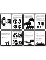
The J101 and J102 cables require correct orientation for
connection. Connect the connectors with white tape to the
PO
W
ER SUPPLY Unit.
Blue
G
N
D
AC Inlet
Notes on Lead Dressing
Note:
The wiring shown in the photo is different from the actual wiring, because the product in the photo is a prototype.
Upon servicing, be sure to restore the original wiring of the unit after repair work.
FA
N
Assy
Notes on Removing the POWER SUPPLY Unit
Discharge of residual electric charge
Immediately after the power cord is unplugged, residual electric charge remains for about 3-5 minutes in the capacitor inside
the PO
W
ER SUPPLY Unit.
Before removing the PO
W
ER SUPPLY Unit, make sure that residual electric charge has fallen to a safe level.
How to discharge residual electric charge rapidly
Discharge residual electric charge by connecting two 220
Ω
(10
W
) forced discharging resistors (440
Ω
in total,) one to each
end, of C101.
<How to remove the POWER SUPPLY Unit>
1
Make sure that the power cord is unplugged. Check the voltage of both ends of C101, using a tester.
2
W
ait until the voltage at both ends of C101 has fallen to 5
V
or less.
3
W
hen the voltage becomes less than 5
V
, disconnect the connectors of the PO
W
ER SUPPLY Unit then remove it.
POWER SUPPLY Unit
Points of checking residual
electric charges:
After making sure that the voltage
of both ends of C101 has fallen
to 5
V
or less, remove the PO
W
ER
SUPPLY Unit.
Содержание KURO KRP-500P
Страница 11: ...11 KRP 500P 5 6 7 8 5 6 7 8 A B C D E F 2 3 PANEL FACILITIES WYSIXK5 and WYS5 types only LFT and WA5 types ...
Страница 12: ...12 KRP 500P 1 2 3 4 A B C D E F 1 2 3 4 Remote Control Unit for WYSIXK5 and WYS5 types ...
Страница 13: ...13 KRP 500P 5 6 7 8 5 6 7 8 A B C D E F Remote Control Unit for LFT type ...
Страница 14: ...14 KRP 500P 1 2 3 4 A B C D E F 1 2 3 4 Remote Control Unit for WA5 type ...
Страница 19: ...19 KRP 500P 5 6 7 8 5 6 7 8 A B C D E F ...
Страница 20: ...20 KRP 500P 1 2 3 4 A B C D E F 1 2 3 4 4 BLOCK DIAGRAM 4 1 OVERALL WIRING DIAGRAM 1 2 ...
Страница 22: ...22 KRP 500P 1 2 3 4 A B C D E F 1 2 3 4 4 2 OVERALL WIRING DIAGRAM 2 2 ...
Страница 23: ...23 KRP 500P 5 6 7 8 5 6 7 8 A B C D E F OVERALL DIAGRAM KRP 500P ...
Страница 139: ...139 KRP 500P 5 6 7 8 5 6 7 8 A B C D E F ...
Страница 148: ...148 KRP 500P 1 2 3 4 A B C D E F 1 2 3 4 9 5 REAR SECTION POWER SUPPLY P8 Refer to 9 6 FRONT SECTION ...
Страница 156: ...156 KRP 500P 1 2 3 4 A B C D E F 1 2 3 4 9 9 PANEL CHASSIS SECTION ...


