- 2 -
Funktionsbeschreibung
Das Gerät erfasst die in der Motorwicklung
induzierte Spannung U
M
, die beim Auslaufen
der Motorwelle entsteht. Wenn die Spannung
den eingestellten Ansprechwert U
an
unter-
schreitet, meldet das S1SW P Stillstand.
Nach dem Einschalten der Versorgungs-
spannung U
B
und bei Motorstillstand (U
M
<
U
an
) ziehen die Ausgangsrelais K1 und K2
an. Nach Anlauf des Motors fällt K1 ab (U
M
>
U
ab
). Der weitere Ablauf ist abhängig von der
verwendeten Betriebsart.
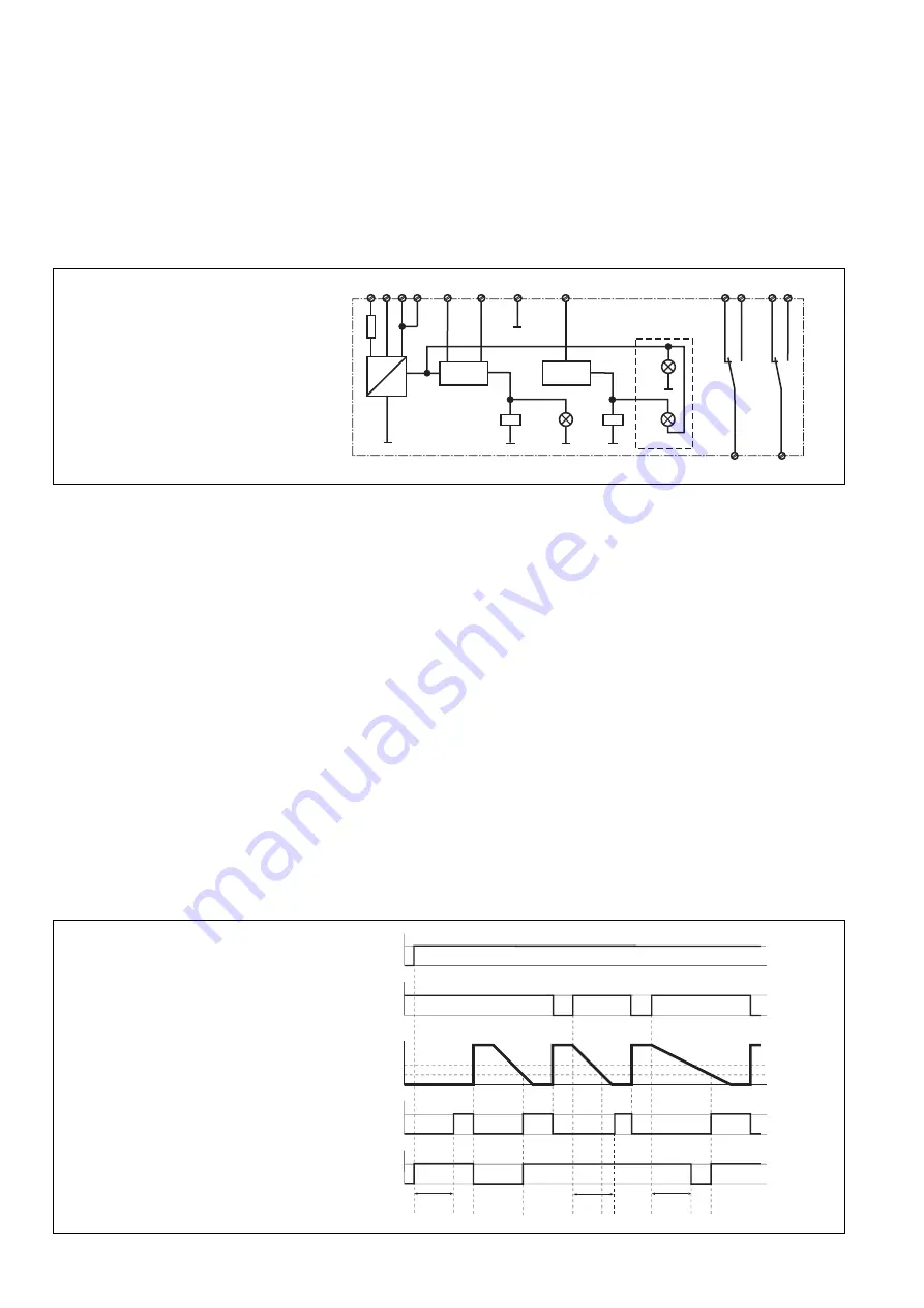
Fig. 2: Funktionsdiagramm/Pulse diagram/
Diagramme fonctionnel
Fig. 1: Schematisches Schaltbild/Wiring
diagram/Schéma interne
Betriebsarten
• Stillstandsüberwachung ohne Auslauf-
überwachung
Die Klemmen Y3-Y4 sind gebrückt.
Das Relais K1 zieht wieder an, wenn der
Motor abgeschaltet und die vom Motor
induzierte Spannung U
M
den Ansprechwert
U
an
unterschreitet (Stillstand). Der
Hilfskontakt 11-12 öffnet, 11-14 schließt.
• Stillstands- und Auslaufüberwachung
An die Klemmen Y3-Y4 ist der Öffner-
kontakt des Motorschützes angeschlos-
sen.
Durch Abschalten des Motors wird der
Öffnerkontakt des Motorschützes ge-
schlossen und dadurch wird die
Auslaufüberwachungszeit t
a
gestartet.
Wenn die vom Motor induzierte Spannung
U
M
innerhalb dieser Überwachungszeit den
Ansprechwert U
an
unterschreitet, zieht
Relais K1 an. Der Hilfskontakt 11-12
öffnet, 11-14 schließt. Wenn die Spannung
nach Ablauf der Überwachungszeit noch
größer als der Ansprechwert U
an
ist, fällt
Relais K2 ab. Der Hilfskontakt 21-24
öffnet, 21-22 schließt.
~
=
+
K1
14
11
21
K2
12
24
22
U
M
< U
an
t < t
a
Y4
A1
Y3
U
V
B3 A2
K1
K2
Stand-
still
(gr)
Flt
(rd)
Pwr
(gr)
A2
U
B
U
an
U
ab
U
M
ta
ta
K1
K2
Y3-Y4
ta
Function description
The device measures the regenerated
voltage U
M
induced from the motor during the
rundown period. If voltage falls below the set
response value U
an
, the S1SW P will detect
standstill.
Once the operating voltage U
B
has been
applied and the motor is at standstill (U
M
<
U
an
), the output relays K1 and K2 energise.
Once he motor has started (U
M
> U
ab
), the
output relays de-energise. An additional
cycle will depend on the type of operating
mode used.
Operating modes
• Standstill monitoring without rundown
monitoring
Terminals Y3-Y4 are linked.
Relay K1 energises again if the motor is
switched off and the induced voltage U
M
from the motor falls below the response
value U
an
(standstill). The auxiliary contact
11-12 opens and 11-14 closes.
• Standstill and rundown monitoring
The N/C contact of the motor’s relay is
connected to terminals Y3-Y4.
If the motor is switched off the N/C contact
of the motor’s relay is closed and in doing
so rundown monitoring t
a
is started. If the
induced voltage U
M
from the motor falls
below the response value U
an
within the
monitoring time, relay K1 energises. The
auxiliary contact 11-12 opens and 11-14
closes. If the voltage is still greater than
the response value U
an
once monitoring
time has elapsed, the relay K2 de-
energises. The auxiliary contact 21-24
opens and 21-22 closes.
Description du fonctionnement
L’appareil mesure la tension rémanente U
M
qui est générée dans les enroulements du
moteur lors de sa décélération. Lorsque la
tension mesurée passe en dessous de la
valeur d’enclenchement définie U
an
, le
S1SW P signale l’arrêt.
A la mise sous tension du relais U
B
et en cas
d’arrêt du moteur (U
M
< U
an
), les relais de
sortie K1 et K2 passent en position travail.
Après le démarrage du moteur, K1 retombe
(U
M
> U
ab
). Le déroulement ultérieur dépend
du mode de fonctionnement utilisé.
Modes de fonctionnement
• Contrôle de l’arrêt sans contrôle du temps
d’arrêt
Les bornes Y3-Y4 sont pontées.
Le relais K1 repasse en position travail,
lorsque le moteur est coupé et que la
tension U
M
induite par le moteur passe en
dessous de la valeur d’enclenchement U
an
(arrêt). Le contact d’information 11-9
s’ouvre, 11-10 se ferme.
• Contrôle de l’arrêt et du temps d’arrêt
Le contact repos du contacteur moteur est
raccordé au bornes Y3-Y4.
En arrêtant le moteur, le contact repos du
contacteur moteur ferme le circuit aux
bornes Y3-Y4, ce qui déclenche le début
de la durée de contrôle du temps d’arrêt t
a
.
Si la tension U
M
induite par le moteur au
cours de cette durée de contrôle passe en
dessous de la valeur d’enclenchement U
an
,
le relais K1 passe en position travail. Le
contact d’information 11-12 s’ouvre,
11-14 se ferme. Si la tension est encore
supérieure à la valeur d’enclenchement
U
an
à l’issue de la durée de contrôle, le
relais K2 retombe. Le contact d’informa-
tion 21-24 s’ouvre, 21-22 se ferme.


