background image

PDS-60  Product Guide

7

211 mm (8.3 in)

mounting slots

51 mm (2 in)

25 mm (1 in)

20 mm (.8 in

)

DMX/ETHERNE

T

IN

DM
X

OU
T

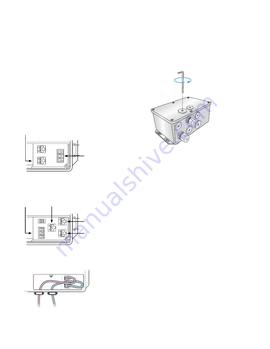
Prepare Cable Connections

1.   Using a Philips screwdriver, loosen the housing cover’s six screws to open the 

PDS-60 housing.

2.   Identify which openings to use for power and data cables, and using an 8 mm 

hex wrench or adjustable wrench, place the included sealing plugs and rings in 

the unused openings. Make sure that the sealing rings are seated correctly. Use 

RTV silicone if installing in damp or wet locations.

3.    Torque the sealing plugs to approximately 2.2 Nm (19 in-lb).

4.  Install and tighten cable connectors or conduit to manufacturer’s specs in the 

remaining openings. Do not overtighten. 
•  For installations using US trade size conduit, the larger openings 

accommodate 3/4 in NPT cable connectors for power, and the smaller 

openings accommodate 1/2 in NPT cable connectors for data.

Make Data Input Connections

PDS-60 has different layouts for data connection ports, depending on the version 

you have. See the illustrations on the left as a guide to the port locations in the 

connection chamber. 
The PDS-60 Ethernet / DMX power/data supply listens for data on both the DMX 

and Ethernet input ports. When valid data is detected, PDS-60 automatically 

switches to the appropriate mode. The PDS-60 Pre-Programmed cannot receive 

input from controllers, but it can pass light show data to downstream DMX devices 

using its DMX OUT port.

DMX

1.    Using an RJ45 connector cable, connect your controller’s DMX output port to 

the DMX IN port on the PDS-60 (not applicable for pre-programmed devices).

2.    To add a second power/data supply to your DMX network, connect an RJ45 

cable from the PDS-60 device’s DMX OUT port to the DMX IN port on the 

second PDS-60 device.

3.    If necessary, continue connecting power/data supplies (up to 32 without a repeater). 

Ethernet

•   Using a CAT 5 cable, connect the ETHERNET IN port on the PDS-60 to an 

available port on an Ethernet switch connected to your lighting network. 

DMX/ETHERNET


IN

DM
X

OU
T

1

2

3

O

S

M

DMX/ETHERNET


IN

DM
X

OU
T

DMX/ETHERNET


IN

DM
X

OU
T

Out to next 

PDS-60 DMX

Master PDS-60 Pre-programmed

Slave PDS-60 DMX

In from 

previous 

PDS-60

Out to next 

PDS-60 DMX

DMX Input 

(from controller)

Ethernet  

Input  

(from controller)

DMX Output  

(to next power/

data supply  

in series, or 

termination)

Power  

and Data  

Output  

(to luminaires)

PDS-60 

DMX/Ethernet

Power and Data  

Output  

(to luminaires)

DMX Output  

(to next power/

data supply  

in series, or  

termination)

PDS-60 

Pre-Programmed

In from 

Previous 

PDS-60

Out to next 

PDS-60 

DMX /

Ethernet

211 mm (8.3 in)

mounting slots

51 mm (2 in)

25 mm (1 in)

20 mm (.8 in

)

GND

+24V

GND

DATA

+24V

ETHERNE

T

DMX IN

DMX OU

T

Содержание PDS-60 24 V DMX/Ethernet

Страница 1: ...PDS 60 Versatile power data supply for indoor and outdoor applications ...

Страница 2: ...es A downstream power data supply does not have to be a PDS 60 but can be any DMX based power data supply Instead of attaching luminaires to a Pre Programmed PDS 60 you could opt to use it as an outdoor rated light show controller for downstream power data supplies and luminaires PDS 60 24 V Pre programmed is a versatile power data supply designed for indoor and outdoor LED lighting installations ...

Страница 3: ...iNET compatible third party Ethernet controllers PDS 60 Pre Programmed Internal Data Input RJ 45 input and output connectors PDS 60 DMX Ethernet only Data Output RJ 45 3 pin terminal block PDS 60 DMX Ethernet only Power Input Line neutral ground cable flying leads Power Output 2 pin spring terminal Physical Dimensions Height x Width x Depth 91 x 140 x 224 mm 3 6 x 5 5 x 8 8 in Weight 2 kg 4 5 lb H...

Страница 4: ...or accent lighting perimeter lighting or cove lighting applications Typical DMX installations with luminaires from Philips Color Kinetics use a controller such as iPlayer 3 a Controller Keypad for turning lights on and off and triggering light shows and one or more PDS 60 devices PDS 60 devices can be connected in series to deliver DMX data from a single controller to all connected lights Note tha...

Страница 5: ...ded One insulated ring or spade crimp terminal one 203 mm 8 in connecting wire and one wire nut per C Splash 2 luminaire The included three push wire connectors CAT 5e or better data cable as required The included black magnetic EMI suppression core for the power cable The included two white magnetic EMI suppression cores for luminaire leader cables Power screwdriver for mounting Four screws suita...

Страница 6: ... black suppression core to the power cable Near the end of the cable that connects to the power data supply coil the power cable into a small loop Place the section of the loop where the cord is doubled into the suppression core Be sure the cord is securely in the core s middle Snap the core shut around the doubled cord 2 Attach a white suppression core to the luminaire strand or leader cable atta...

Страница 7: ...th the DMX and Ethernet input ports When valid data is detected PDS 60 automatically switches to the appropriate mode The PDS 60 Pre Programmed cannot receive input from controllers but it can pass light show data to downstream DMX devices using its DMX OUT port DMX 1 Using an RJ45 connector cable connect your controller s DMX output port to the DMX IN port on the PDS 60 not applicable for pre pro...

Страница 8: ...X ETHERNET IN DMX OUT R W B W R R W B B R W B W R R W B B Ground z ColorBurst 6 ColorBlast 6 ColorBlast 12 C Splash 2 R W B R W B R W B R W B R W B DMX ETHERNET IN DMX OUT 1 2 3 O S M DMX ETHERNET IN DMX OUT R W B ColorBurst 6 C Splash 2 ColorBlast 6 DMX ETHERNET IN DMX OUT R W B DMX ETHERNET IN DMX OUT R W B W R R W B B R W B W R R W B B Ground z ColorBurst 6 ColorBlast 6 ColorBlast 12 C Splash 2...

Страница 9: ...ctors 1 Install a cable strain relief connector in one of the device s 3 4 in openings in the power connection chamber If necessary use conduit as required by local electrical codes 2 Run the mains voltage power cable through the opening Pull at least 152 mm 6 in of wire into the chamber 3 Strip at least 10 mm 0 38 in of insulation from the wires Join the mains line wire with the flying leads usin...

Страница 10: ... Button Options Button 1 Rainbow Produces a smooth transition through the color spectrum Colors appear to follow each other from luminaire to luminaire Cycles through four effect speed settings Cycles through four width settings then reverses direction and decreases widths 2 Random Produces a sequence of randomly generated solid colors simultaneously on all fixtures Toggles between immediate and fa...

Страница 11: ... way you would address luminaires in an ordinary DMX network For complete details on addressing and on using QuickPlay Pro refer to the Addressing and Configuration Guide available at www colorkinetics com support addressing Status Indicators Each PDS 60 has between two and five status indicators depending on the version of the device All indicators are located inside the luminaire s housing Power...

Страница 12: ... Remove the blown fuse from its metal clips next to the luminaire and data connection ports see image below 4 Replace the fuse with a new 4 A 5 x 20 fast blow fuse 5 Replace the cover ensuring that the gasket is seated properly and that no wires are pinched 6 Attach the cover with the six included screws Tighten screws to 8 to 10 in lbs 1 in lb 11 2985 N cm If you are installing in a wet or damp l...

Отзывы: