LCD Menu System
15
eS21 LED Raceway
Installation & Operation Guide
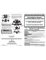
Port DMX Splash Screen 4
Figure 8
is an illustration of Splash Screen 4:
Figure 8: Splash Screen 4
3.
LCD Menu System
The Head-End Processor LCD Display Menu system consists of several main categories. To navigate the menus,
press the four navigation buttons as required (
Figure 4
). When the desired menu is reached, press [Enter] to display
the menu options. Use navigation and [Enter] buttons to view status and configure the LCD Menu as required.
LCD Menu Structure
DMX ADDRESSES
DMX
eS21 Strip:
Mod 1 (LED):
Mod 2 (RLY):
Mod 3 (DMR):
123
10/20/30/40
123/124
125/126
eS21 LED DMR STRIP
Unlocked / Locked Symbol - Menu is unlocked
in this example. If the "Locked" symbol
appears, then a password is required before
changes are accepted.
Screen Name
If the unit is connected to and
seeing a DMX512 signal, this
symbol appears.
eS21 LED Strip DMX Address
DMX Addresses of the LED
Module Ports (if installed)
DMX Addresses of the RELAY
Module Ports (if installed)
DMX Addresses of the DIMMER
Module Ports (if installed)
MAIN MENU
eS21 DMX Start Address
System Status
Module / Port Status
Module / Port Config
Module / Port DMX Addr
System Configuration
Select Local Presets
Edit Local Presets
Menu Configuration
Continued next page
Содержание eS21
Страница 1: ......
Страница 29: ...eS21 LED Raceway 230V 240V Model 71900 27 eS21 LED Raceway Installation Operation Guide Notes ...
Страница 30: ......