background image


2. YDA148 

YDA148 (D-510) is a high-efficiency digital audio power amplifier IC with the maximum output of 15W 

× 2ch. 

YDA148 has a “Pure Pulse Direct Speaker Drive Circuit” that directly drives speakers while reducing 

distortion of pulse output signal and reducing noise on the signal, which realizes the highest standard 

low distortion rate characteristics and low noise characteristics among digital amplifier ICs in the same 

class. 

In addition, supporting filterless design allows circuit design with fewer external parts to be realized 

depending on use conditions. 

YDA148 features Power Limit Function, Non-clip Function, and DRC (Dynamic Range Control) 

Function that were developed by Yamaha original digital amplifier technology. 

YDA148 has overcurrent protection function for speaker output terminals, high temperature protection 

function, and lowsupply voltage malfunction prevention function. 


3. 61P803-RG480WT 

¾


ҏ

Embedded Turbo 8052 CPU 

¾


ҏ

Normal operation mode: 12MHz, 6MHz, 3MHz, 1MHz (Selectable Clock Sources) 

¾


ҏ

Instruction execution time : Min. =250ns at OSC=12Mhz 

¾


ҏ

Memory: 

¾


ҏ

RAM: 1K+256 Bytes 

¾


ҏ

Flash memory : 48K Bytes 

¾


ҏ

5 similar 8052 timers: Timer0, Timer1, Timer2, Timer3, Timer4 

¾


ҏ

3 similar 8052 UART ports, support baud rate 115200 – 1200 at OSC = 12MHz 

Philips BDL5545E   36 

Содержание BDL5545E

Страница 1: ...SERVICE MANUAL BDL5545E ...

Страница 2: ...G 3 CHAPTER C SEFETY RRECAUTIONS 4 CHAPTER 1 GENERAL SPECIFICATION 5 CHAPTER 2 OPEARTING INSTRUCTION 14 CHAPTER 3 THEORY OF OPERATION 35 CHAPTER 4 BLOCK DIAGRAM 38 CHAPTER 5 SCHEMATIC DIAGRAM 39 CHAPTER 6 LAYOUT SIDE VIEW 40 CHAPTER 7 EXPLODED VIEW 41 CHAPTER 8 TROUBLE SHOOTING 42 ...

Страница 3: ...Philips BDL5545E 2 CHAPTER A REVISION LIST Model Name Version Issues Date Remark BDL5545E 3A 2011 11 08 First Release ...

Страница 4: ...contain warnings or cautions to advise non technical individuals of potential dangers in attempting to service a product Products powered by electricity should be serviced or repaired only by experienced professional technicians Any attempt to service or repair the product or products dealt within this service information by anyone else could result in serious injury or death ...

Страница 5: ...et Do not use an isolation transformer during this check 4 2 Connect a 1500 ohm 10 watt resistor paralleled by a 0 15uF capacitor between each metallic part and a good earth ground 4 3 Use an AC voltmeter with 1000 ohm volt or more sensitivity and measure the AC voltage across the combination 1500 ohm resistor and 0 15uF capacitor 4 4 Move the resistor connection to each exposed metallic part and ...

Страница 6: ...ontal 178 Vertical 178 Response Time 8 ms GTG Frequency Horizontal 15 91 KHz Vertical 50 85 Hz Pixel Clock 13 5 165 0 MHz Speaker External speaker jack 7W 7W Internal speaker 10W 10W Power Supply 100 240 VAC 50 60 Hz Power Consumption Display mode 350 W typical 400 W max Sleeping mode Less than 1 W Operational Environment Temperature 0 40 C Humidity 20 80 Storage Environment Temperature 20 60 C Hu...

Страница 7: ...2 Outline Front view Rear view Philips BDL5545E 6 ...

Страница 8: ... Side view Left Right Top view Button view Philips BDL5545E 7 ...

Страница 9: ...r HDMI jack SPEAKERS R L Outputs the audio signal from the AUDIO IN AUDIO1 AUDIO2 AUDIO3 or HDMI jack to external speakers Main power switch Press to switch the mains power on off AC OUT Connect to the AC IN socket of an external media device Rating 100 240Vac 50 60Hz 3A Max AC IN Connect the supplied power cord to the wall outlet DISPLAY PORT Connects to the DisplayPort output of a PC or an AV de...

Страница 10: ...MI output of an AV device Using a DVI HDMI cable VGA IN Connects to the VGA output of a computer VGA OUT Outputs the VGA signal from the VGA IN jack VIDEO IN COMPONENT Component video input Component for connecting to the component output of an AV device Philips BDL5545E 9 ...

Страница 11: ... 13 H Sync 14 V Sync 15 DDC Clock SCL DVI D Pin No Signal name 1 TMDS data2 2 TMDS data2 3 TMDS data2 shield 4 NC 5 NC 6 DDC clock 7 DDC data 8 Analog vertical sync 9 TMDS data1 10 TMDS data1 11 TMDS data1 shield 12 NC 13 NC 14 5V power 15 Ground return for 5 V and H V sync 16 Hot plug detect 17 TMDS data0 18 TMDS data0 19 TMDS data0 shield 20 NC 21 NC 22 TMDS data clock shield 23 TMDS data clock ...

Страница 12: ...17 DDC CEC Ground 18 5V Power 19 Hot Plug Detect Display Port Pin No Type Signal name 1 In ML_Lane 3 n 2 GND Ground 3 In ML_Lane 3 p 4 In ML_Lane 2 n 5 GND Ground 6 In ML_Lane 2 p 7 In ML_Lane 1 n 8 GND Ground 9 In ML_Lane 1 p 10 In ML_Lane 0 n 11 GND Ground 12 In ML_Lane 0 p 13 GND Ground 14 GND Ground 15 I O AUX CH p 16 GND Ground 17 I O AUX CH n 18 Out Hot Plug Detect 19 RTN Return 20 Power Out...

Страница 13: ...Philips BDL5545E 12 RS 232C Pin No Signal name 1 NC 2 RXD 3 TXD 4 NC 5 GND 6 NC 7 NC 8 NC 9 NC ...

Страница 14: ... 67 5 75 000 108 000 13 CVT 2 3MA 1280 x768 47 776 59 870 79 500 NEG POS 14 VESA 1280x960 60 60 000 108 000 15 VESA 1280x1024 63 981 60 020 108 000 16 VESA 1280x1024 79 976 75 025 135 000 17 VESA Standard AddDMT 1360x768 47 712 60 015 85 500 18 VESA Standard AddDMT 1366x768 47 712 59 790 85 500 NEG POS 19 VESA 1440x900 55 935 59 887 106 500 NEG POS 20 CVT AddDMT 1440x1050 65 3 60 000 121 750 21 CV...

Страница 15: ...it LCD power status indicator Indicates the operating status of the display Lights green when the display is turned on Lights red when the display is in standby mode Lights amber when the display enters DPMS mode When SCHEDULE is enabled the light blinks green and red If the indicator blinks red that a failure has been detected Off when the main power of the display is turned off OPS power status ...

Страница 16: ...utton ˉ To decrease the adjustment while OSD menu is on or to decrease the audio output level while the OSD menu is off UP button S To move the highlight bar up to adjust the selected item while OSD menu is on DOWN button T To move the highlight bar down to adjust the selected item while OSD menu is on MENU button Activates the OSD Menu Once OSD is activated pressing this button will return to the...

Страница 17: ...STOM DYNAMIC or REAL CONTRAST button To start CONTRAST OSD selection and then push or button to adjust the value DISPLAY button To turn on off the setting information displayed on the right up corner of the screen MINUS button To increase or decrease a selected value with the OSD menu To move the sub picture left when in PIP mode SET button To activate the setting with the OSD menu AUTO ADJUST but...

Страница 18: ... the highlight bar up to adjust the selected item when OSD menu is on To move the sub picture up when in PIP mode MENU button To turn the OSD menu on off PLUS button To increase or decrease a selected value with the OSD menu To move the sub picture right when in PIP mode EXIT button To turn to the previous OSD menu DOWN button To move the highlight bar down to adjust the selected item when OSD men...

Страница 19: ...level Adjust to change the image brightness Press the SET PLUS button to open the submenu and then press the PLUS MINUS button to adjust Noise reduction Adjust to remove the noise in the image thereby enhancing the detail of your images Select a suitable noise reduction level Press the SET PLUS button to open the submenu and then press the UP DOWN button to toggle between x Off x Low x Middle x Hi...

Страница 20: ...the R Red G Green and B Blue settings independently Press the SET PLUS button to open the submenu Press the UP DOWN button to select User R User G or User B and press the PLUS MINUS button to adjust Light sensor Choose to enable or disable the ambient light sensor Once enabled the image brightness will be adjusted automatically when ambient lighting condition changes Press the SET PLUS button to o...

Страница 21: ...SET PLUS button to open the submenu and then press the PLUS MINUS button to make selection Select Reset and press the SET button to restore settings to factory preset values Press the EXIT button or select Cancel and press the SET button to cancel and then return to the previous menu ...

Страница 22: ... open the submenu and then press the PLUS MINUS button to adjust Press the PLUS button to expand the width of the image or press the MINUS button to shrink the width of the image Clock phase Note For VGA input only Adjust to improve the focus clarity and stability of the image Press the SET PLUS button to open the submenu and then press the PLUS MINUS button to adjust Zoom mode The pictures you re...

Страница 23: ...an use this function to further customize the zoom settings to suit the image you want to display Press the SET PLUS button to open the submenu Use the UP DOWN button to toggle between the following items and use the PLUS MINUS button to adjust x Zoom Expands the horizontal and vertical sizes of the image simultaneously x H zoom Expands the horizontal size of the image only x V zoom Expands the ve...

Страница 24: ...rease or decrease higher pitched sounds Press the SET PLUS button to open the submenu and then press the PLUS MINUS button to adjust Bass Adjust to increase or decrease lower pitched sounds Press the SET PLUS button to open the submenu and then press the PLUS MINUS button to adjust Mute To turn the mute function on off Press the SET PLUS button to open the submenu and then press the UP DOWN button...

Страница 25: ...T PLUS button to open the submenu and then press the PLUS MINUS button to make selection Select Reset and press the SET button to restore settings to factory preset values Press the EXIT button or select Cancel and press the SET button to cancel and then return to the previous menu ...

Страница 26: ...ize Select the size of the sub picture in the PIP Picture in Picture mode Press the SET PLUS button to open the submenu and then press the UP DOWN button to toggle between x Small x Medium x Large PIP audio Select the audio source in the PIP Picture in Picture mode Press the SET PLUS button to open the submenu and then press the UP DOWN button to toggle between x MAIN Select audio from the main pi...

Страница 27: ... combinations as shown in the table below Main picture signal source DP HDMI DVI D Card OPS VGA Component DP x o o o x x HDMI o x x x o o DVI D o x x x o o Card OPS o x x x o o VGA x o o o x x Sub picture signal source Component x o o o x x o PIP function available x PIP function unavailable x The availability of the PIP function will also depend on the resolution of the input signal being used ...

Страница 28: ...ust Power save Set the display to reduce the power automatically Press the SET PLUS button to open the submenu and then press the UP DOWN button to toggle between x PC Select ON to make the monitor enter DPMS mode Display Power Management Signaling when no signal can be detected from the DisplayPort HDMI DVI D and VGA inputs after three successive cycles Use the PLUS MINUS button to make selection...

Страница 29: ...or ghost images which will decrease the quality of your images In some instances ghost image damage can be permanent Ghost imaging is also not covered by warranty so in order to avoid such issues we strongly recommend one of the following actions x Change the picture periodically x Enable Pixel shift See Pixel shift under Section 4 2 5 CONFIGURATION 1 MENU x Use a screen saver with changing image ...

Страница 30: ...he SET PLUS button to open the submenu and then press the UP DOWN button to adjust Note When the Sleep timer is activated Schedule settings will be disabled OSD rotation Adjust the orientation of the OSD menu Press the SET PLUS button to open the submenu and then press the UP DOWN button to adjust between 0 90 180 and 270 degrees OSD H position Adjust the horizontal position of the OSD menu Press ...

Страница 31: ...xpansion Note For Video mode inputs only This feature offers deeper blacks for an even better image quality Select a suitable black level expansion setting to reveal more details in the dark parts of an image Press the SET PLUS button to open the submenu and then press the UP DOWN button to toggle between x Off x Low x Medium x High Gamma selection Gamma is what controls the overall brightness of ...

Страница 32: ...enu and then press the UP DOWN button to toggle between x Auto Enable the film mode frame conversion function for movies and motion pictures The display converts a 24 frames per second 24 fps input signal format to DVD video signal format Once this function is enabled it is recommended that you set the Scan conversion function to Progressive x Off Disable the film mode frame conversion function Th...

Страница 33: ...4 displays H displays 2 V displays 2 5 x 5 screen matrix 25 displays H displays 5 V displays 5 Position Position V monitors V monitors x H monitors Select the number of displays on the horizontal side x V monitors Select the number of displays on the vertical side x Position Select the position of this display in the screen matrix x Frame comp Choose to turn on or off the frame compensation functi...

Страница 34: ...ed time intervals for the display You can select the time the displayturns on and turns off the days in a week the displayis activated and which input source the displaywill use for each scheduled activation period 1 Press the SET PLUS button to open the submenu 2 Press the UP DOWN button to select a schedule item item 1 through item 7 and then press the PLUS button 3 With the ON item highlighted ...

Страница 35: ...ess the UP DOWN button to make selection HDMI with One Wire This function gives you the ability to control your display through the HDMI connector using CEC Consumer Electronics Control commands Press the SET PLUS button to open the submenu and then press the UP DOWN button to make selection Smart power Set the displayto reduce the power consumption automatically Press the SET PLUS button to open ...

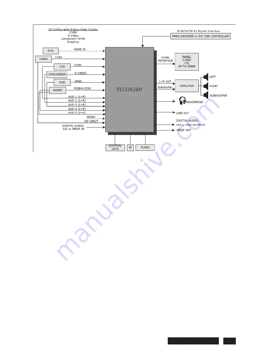
Страница 36: ...l of video quality technology only seen on Faroudja Home Theater Systems in the past is now available in a single chip solution The integrated VBI dataslicer and video decoder remove the need for external components resulting in significant cost reduction The FLI32626H supports many worldwide VBI standards for applications of Teletext Closed Captioning V Chip and other VBI services The audio decod...

Страница 37: ...realized depending on use conditions YDA148 features Power Limit Function Non clip Function and DRC Dynamic Range Control Function that were developed by Yamaha original digital amplifier technology YDA148 has overcurrent protection function for speaker output terminals high temperature protection function and lowsupply voltage malfunction prevention function 3 61P803 RG480WT ҏEmbedded Turbo 8052 ...

Страница 38: ...aturing a high level of integration and low power consumption The ARM Cortex M3 is a next generation core that offers system enhancements such as enhanced debug features and a higher level of support block integration The LPC1768 67 66 65 64 63 operate at CPU frequencies of up to 100 MHz The LPC1769 operates at CPU frequencies of up to 120 MHz The ARM Cortex M3 CPU incorporates a 3 stage pipeline ...

Страница 39: ...PTER 4 BLOCK DIAGRAM Index of this chapter 1 Wiring diagram 2 Block diagram Please refer to the attached Block Diagram 1 Wiring diagram 2 Block diagram LULQJ LDJUDP SGI ORFN GLDJUDP SGI Philips BDL5545E 38 ...

Страница 40: ...7 Power board Please refer to the attached Schematic Diagram 1 Main board 2 Button board 3 Sensor board LUFXLWB0DLQ ERDUG SGI LUFXLWB XWWRQ ERDUG SGI LUFXLWB6HQVRU ERDUG SGI 4 I O board 5 LED board 6 Interface board LUFXLWB 2 ERDUG SGI LUFXLWB ERDUG SGI LUFXLWB QWHUIDFH ERDUG SGI 7 Power board LUFXLWB3RZHU ERDUG SGI Philips BDL5545E 39 ...

Страница 41: ...rd 7 Power board Please refer to the attached Layout Side View 1 Main board 2 Button board 3 Sensor board D RXWB0DLQ ERDUG SGI D RXWB XWWRQ ERDUG SGI D RXWB6HQVRU ERDUG SGI 4 I O board 5 LED board 6 Interface board D RXWB 2 ERDUG SGI D RXWB ERDUG SGI D RXWB QWHUIDFH ERDUG SGI 7 Power board D RXWB3RZHU ERDUG SGI Philips BDL5545E 40 ...

Страница 42: ...CHAPTER 7 EXPLODED VIEW Index of this chapter 1 Exploded view Please refer to the attached Exploded View 1 Exploded view SORGHG YLHZ SGI Philips BDL5545E 41 ...

Страница 43: ... mode always show No Signal 5 Video mode always show No Signal 1 No Power Check LED whether LED is on or not Check M B L45 1 2V correct No Change M B Yes Yes No Change IO B Separate IO B connect M B and Power B J3 pin5 5V correct Separate M B J3 pin5 5V correct Yes Change IO B No No Change M B No Power Philips BDL5545E 42 ...

Страница 44: ...2 No Picture No Backlight No Change M B No Check LCD Panel Yes Change Power B Check Power B CN8 pin11 3 3V correct No Picture No Backlight Philips BDL5545E 43 ...

Страница 45: ... pin1 5 12V correct Check LVDS cable Check LCD Panel Yes Yes Change M B Change LVDS cable Check IF B L24 5V correct Check IF B to LCD cable Yes Yes No No No No Change IF B to LED cable Change IF B No Characters Missing Color Philips BDL5545E 44 ...

Страница 46: ...ode always show No Signal Check VGA cable correct Check M B input CN5 pin13 H sync and pin14 V sync correct Yes No Check PC Yes No Change M B Change VGA cable VGA mode always show No Signal Philips BDL5545E 45 ...

Страница 47: ...5 Video mode always show No Signal No Change Video cable Yes Change IO B Check Video cable correct Video mode always show No Signal Philips BDL5545E 46 ...

Отзывы: