12
1
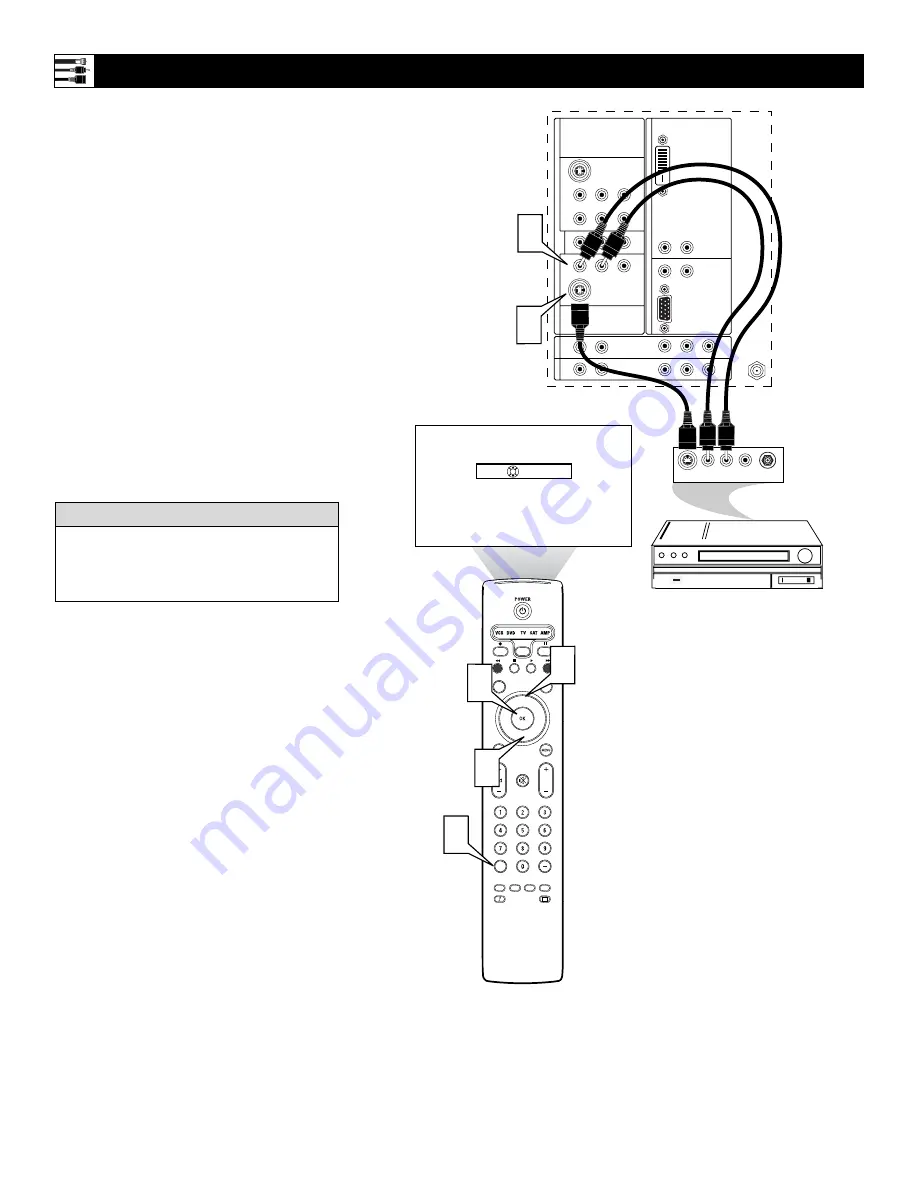
Using an S-Video cable, connect to the
S-Video output on the back of the
S-Video device and to the AV2 S-
VIDEO input.
2
Using Stereo Audio cables, connect to
the AUDIO OUT jacks on the back of
the
S-Video device and to the correspon-
ding AV2 audio inputs (L and R).
3
Press the AV+ button on the remote
control to access the Source list.
4
Press the Cursor Up or Down button to
select the AV2 input source.
5
Press the OK button to confirm your
choice. The set is now switched to the
AV2 input source for the viewing of
programs from the S-Video device.
Connecting an S-Video Device
®
®
®
®
SAP
CONTROL
TIMER
ACTIVE
SLEEP
CLOCK
AV+
PIP
SCREEN
FORMAT
SURF
TV
SURR
HD
INFO
SELECT
DNM
CC
AUTO
AUTO
P
DVI
G
S-VIDEO
G
S-VIDEO
R
L
V
R
L
R
L
R
L
V
Pr
Pb
Y
R
L
R
L
Pr
Pb
Y
Pr
Pb
Y
R
L
V
STANDARD/
HD INPUTS
STANDARD/
HD INPUTS
TUNER
RGB+HV
AV
5
A
V
6
AV
1
MON
SUB OUT
A
V
2
AV
3
AV
4
OUT
SER
V
ICE 1
2
C
Source
OK
AUDIO OUT
L R
S-VIDEO
OUT
ANT/CABLE
IN
VIDEO
OUT
2
1
5
3
4
4
TV
AV1:Other
AV2:Other
AV3:Other
AV4:Other
AV5:Other
AV6:Other
SIDE:Other
Back of Standard S-Video Device
(example only)
Back of TV
To simplify making connections, the connec-
tors on audio and video cables are often color
coded to match the colors on TV jacks, red for
right, and white for left.
H
ELPFUL
H
INT


