background image


NewFEIMAS


Refer to Revision Record on page 2. 

T.Anzai 

Nov. 20, 2008 

K.Okada 

Rev


04 


03 

PAGE 

50

/

138


PFU LIMITED


P1PA03334-B30X/6


  Refer to Revision Record on page 2. 

T.Anzai 

July 7, 2008 

K.Okada 

  Refer to Revision Record on page 2. 
 

K.Okada 


K.Okada 

DESCRIPTION 

CHECK 

DATE 

T.Anzai 

APPR. 

   K.Okada 

K.Okada 

Aug.19, 2005 

DESIG

N

DESIG


CUST. 

I.Fujioka 


I.Fujioka 

T.Anzai 


CHECK 

fi-5530C/fi-5530C2

 IMAGE SCANNER


MAINTENANCE MANUAL


APPR. 

TITLE


DRAW. 

No.


Feb.23, 2007 

05 


Section 3-3-4 

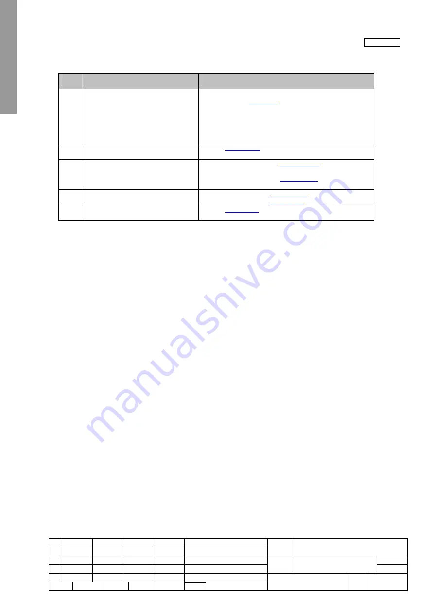
3-3-4. Resolution or gradation of scanned image is unsatisfactory 


Table 3-3-4 

Item 

No. 

Check items 

How/where to check 

Check the items listed in the right 
column. 


Does the document satisfy the paper specifications 
described in 

Section 1-2


Are the scan settings (resolution or density) correctly 
specified for the application software used? 


Is interface cable correctly connected? 


If any temporary error or alarm is indicated, follow the 
corresponding troubleshooting. 

Clean feed rollers and plastic roller and 
check whether the error is resolved. 

Refer to 

Section 1-7-1

Is the optical unit or lamp dirty? Are the 
cables damaged? Or are the connectors 
connected correctly?   

ADF front scanning: See 

Section 4-10-6

 for cleaning and 

checking. 
ADF back scanning: See 

Section 4-9-3

 for cleaning and 

checking. 

Replace Optical unit and see if the error 
is resolved. 

ADF front scanning: See 

Section 4-10-6

 for replacement. 

ADF back scanning: See 

Section 4-9-3

 for replacement. 

Replace Control PCA and see if the error 
is resolved. 

Refer to 

Section 4-11


Содержание fi-5530C

Страница 1: ...donpage2 T Anzai July7 2008 K Okada RefertoRevisionRecordonpage2 K Oakda K Okada DESCRIPTION CHECK DATE T Anzai APPR K Okada K Okada Aug 19 2005 DESIG N DESIG CUST I Fujioka I Fujioka T Anzai CHECK fi...

Страница 2: ...aft 01 May 27 2005 Draft 01 released Draft 02 July 8 2005 Draft 02 released 01 August 19 2005 01 version released 02 February 20 2006 P39 117 123 125 126 For RoHS compliance etc P117 131 AC Cordset UK...

Страница 3: ...Getting Started P3PC 1342 EN A booklet attached to scanner 3 fi 5530C fi 5530C2 Illustrated Parts Catalog P4PA03334 B30X 6 4 fi 5530C2 Operator s Guide P3PC 1922 EN A CD ROM attached to scanner 5 fi 5...

Страница 4: ...oft Windows 95 operating system Windows 98 Microsoft Windows 98 operating system Windows Me Microsoft Windows Millennium Edition operating system Windows NT 4 0 Microsoft Windows NT 4 0 Server operati...

Страница 5: ...THE CONSUMABLES 28 1 8 1 Consumables 28 1 8 2 Replacing Pad ASSY 28 1 8 3 Replacing Pick roller 30 1 8 4 Resetting Consumable Counters 33 CHAPTER 2 DESCRIPTION OF SCANNER OPERATION 34 2 1 ADF UNIT 34...

Страница 6: ...SSEMBLY PARTS 64 4 6 RESERVED 64 4 7 REMOVING MOUNTING CHUTE UNIT STACKER UNIT PCB UNIT AND COVERS 65 4 7 1 Removing Mounting the Chute unit ADF paper chute 65 4 7 2 Removing Mounting the Stacker Unit...

Страница 7: ...splay 109 5 1 8 Maintenance mode 7 EEPROM data restore 111 5 2 SAVING EEPROM DATA 112 5 3 EMULATION MODE 113 CHAPTER 6 MAINTENANCE PARTS 116 6 1 BASE UNIT 117 6 2 DUST COVER 117 6 3 HK RING SR 118 6 4...

Страница 8: ...r 24bit Gray 8bit Monochrome 1bit 6 Document ADF scanning Size Max A3 or 11 x 17 Min A8 Portrait 53 x 74 mm Thickness 52 to 127 g m2 14 to 34 lb 7 Capacity of hopper 100 sheets A4 80g m2 or 20lb 50 sh...

Страница 9: ...the ADF 5 Operator panel Used for operating the scanner The scanner status is indicated on the Function No Display Panel 6 Stacker Documents are stacked here after they are scanned Back No Parts name...

Страница 10: ...K Okada RefertoRevisionRecordonpage2 K Okada K Okada DESCRIPTION CHECK DATE T Anzai APPR K Okada K Okada Aug 19 2005 DESIG N DESIG CUST I Fujioka I Fujioka T Anzai CHECK fi 5530C fi 5530C2IMAGE SCANNE...

Страница 11: ...Function Changes the Function activated by the Send to button Send to Scan Launches the linked application software Button Power button Turns the scanner ON and OFF LED Lights when the scanner is tur...

Страница 12: ...RevisionRecordonpage2 T Anzai July7 2008 K Okada RefertoRevisionRecordonpage2 K Okada K Okada DESCRIPTION CHECK DATE T Anzai APPR K Okada K Okada Aug 19 2005 DESIG N DESIG CUST I Fujioka I Fujioka T A...

Страница 13: ...onpage2 K Okada K Okada DESCRIPTION CHECK DATE T Anzai APPR K Okada K Okada Aug 19 2005 DESIG N DESIG CUST I Fujioka I Fujioka T Anzai CHECK fi 5530C fi 5530C2IMAGE SCANNER MAINTENANCE MANUAL APPR TIT...

Страница 14: ...g envelopes Wrinkled or curled documents See right figure Folded or torn documents Tracing paper Coated paper Carbon paper Carbonless paper Photosensitive paper Perforated or punched documents Docume...

Страница 15: ...K DATE T Anzai APPR K Okada K Okada Aug 19 2005 DESIG N DESIG CUST I Fujioka I Fujioka T Anzai CHECK fi 5530C fi 5530C2IMAGE SCANNER MAINTENANCE MANUAL APPR TITLE DRAW No Feb 23 2007 05 Section 1 2 3...

Страница 16: ...cordonpage2 K Okada K Okada DESCRIPTION CHECK DATE T Anzai APPR K Okada K Okada Aug 19 2005 DESIG N DESIG CUST I Fujioka I Fujioka T Anzai CHECK fi 5530C fi 5530C2IMAGE SCANNER MAINTENANCE MANUAL APPR...

Страница 17: ...the vertical centerline of the document Other paper shall not be glued within 35 mm 1 4 in of the vertical centerline of the document 2 Check length Document length deviation 1 or less Punched holes a...

Страница 18: ...t AC Adapter Chute unit ADF paper chute Control PCA AC Cable Stacker unit Base unit Optical Section ADF Pick roller Pick Motor Rear cover OPT unit with Cable F Lamp SR Inverter SR Upper unit Lock ADF...

Страница 19: ...ge Make sure that all the accessories are included in the package 1 Remove the tape to open the package box 2 Take out the CD tray and other accessories 3 Take out the scanner and cushions And remove...

Страница 20: ...ations in Section 1 1 Overview 2 Attach the ADF paper chute Chute unit by referring to Section 4 7 1 3 Connect the AC adapter Use only the AC adapter provided by the manufacturer 1 Connect the AC cabl...

Страница 21: ...a SCSI daisy chain formation connect the scanner so that it is the terminated device Be careful not to bend the pins of the SCSI cable when connecting to the scanner 5 SCSI ID initially set at the fac...

Страница 22: ...ation of the Function No Display changes as follows 8 P 0 1 The indication 1 means that the operator panel is in the ready status 2 Turning OFF the power Hold the power button at least two seconds Pow...

Страница 23: ...size paper that makes a document stack of 5mm or less 50 sheets at 80g m2 or at 20 lb 2 Fan the document as follows 1 Lightly grip both ends of the documents with both hands and bend the documents as...

Страница 24: ...paper chute Chute unit extension according to the lengths of the documents 5 Adjust the side guides to the width of the documents Move the side guides so that they touch both sides of the documents If...

Страница 25: ...dapter from the power outlet and wait at least 15 minutes Do not turn off the scanner when you clean the Feed Rollers and Eject rollers Clean the ADF after every 5 000 scans Without periodical cleanin...

Страница 26: ...ADF when the indication of the Function Number display is not P or 0 If you open the ADF when the indication of the Function Number display is P or 0 the Feed rollers Eject rollers will not rotate eve...

Страница 27: ...ujioka T Anzai CHECK fi 5530C fi 5530C2IMAGE SCANNER MAINTENANCE MANUAL APPR TITLE DRAW No Feb 23 2007 05 Section 1 7 1 Sheet guide Guide P ASSY Clean lightly Glass Clean lightly Note If the glass is...

Страница 28: ...ications Standard replacement cycle How to check the number of scanned documents How to replace 1 Pad ASSY PA03334 0002 100 000 scans or one year See Section 1 8 2 2 Pick roller PA03334 0001 200 000 s...

Страница 29: ...DRAW No Feb 23 2007 05 Section 1 8 2 3 Remove the Pad ASSY Pinch the Pad ASSY and slide it to the direction of the arrow and remove it 4 Attach new Pad ASSY Insert the claws of the Pad ASSY into the...

Страница 30: ...TLE DRAW No Feb 23 2007 05 ADF paper chute Chute unit Section 1 8 3 1 8 3 Replacing Pick roller Refer to Section 1 8 2 for the specification of the Pick roller 1 Remove all documents from the ADF pape...

Страница 31: ...e Pick roller shaft while lifting it up in the direction of the arrow Note As the Pick roller bushing is firmly fixed do not try to turn the roller bushing with your fingernails Use a paper clip for t...

Страница 32: ...R TITLE DRAW No Feb 23 2007 05 Section 1 8 3 Note Make sure that the Pick roller is correctly attached The incompletely attached Pick roller might cause the document jams or other feed errors When att...

Страница 33: ...10 Reset the pick counter by referring to Section 1 8 4 and Section 5 1 6 1 8 4 Resetting Consumable Counters For Windows 98 Windows Me Windows 2000 Windws XP example Note For Windows 95 Windows NT 4...

Страница 34: ...umables and replaced by user Refer to Section 1 8 1 for detail The scanner supports two consumable counters Pad counter and Pick counter to indicate the number of sheets that have been scanned from th...

Страница 35: ...sufficient CCD output The lamp is turned ON or OFF by Inverter that is controlled by the Control PCA The life of lamp is about 10000 hours which lasts through the life of device So the lamp is not a c...

Страница 36: ...nnector DC voltage input connector SCSI ID setting rotary switch If both SCSI and USB cables are connected SCSI is selected when selection phase is recognized first USB is selected when H level VBUS s...

Страница 37: ...correction value for main sub scanning direction White level correction value Values of Pad counter Pick counter Roller kit counter and Ink remainder counter First date of the scanner operation ADF sc...

Страница 38: ...03 Input 24V dc CCD Board Front Lamp SR Front PA03334 F903 Inverter SR Front PA03334 F916 US Sensor PA03334 F902 Sensor TOP PA03334 F923 Sensor EM 02 PA03334 F907 PA03334 F914 LF Motor 02 PA03334 F90...

Страница 39: ...ys 8 without blinking Immediately after power on scanner turns all the segments ON When the initial processing starts the following display appears Function No Display Power LED Description ON Display...

Страница 40: ...ial check Performs driving test for rollers if no sensor in the ADF detects any paper E4 Motor fuse check E4 9 1 SCSI fuse check E8 1 When 5V 3 3V fuse is blown the scanner does not turn on 3 1 2 Onli...

Страница 41: ...The scanner checks the following errors alarms during maintenance mode and displays the result if any error alarm is detected Maintenance mode No Check items At power on 1 2 2 4 Error display on Scann...

Страница 42: ...sequence Function No Display Power LED Description ON Displays U and the error No 0 9 alternately Example When error U0 occurs the scanner displays the following U 0 When Scan or Send to button is pr...

Страница 43: ...d length to be compared with the length of subsequent documents The scanner detects a multi feed when the detected paper length is larger or smaller than the standard value one out of 10mm 15mm or 20m...

Страница 44: ...rtridge mounted is detected during scanning How to recover Check if the Print Cartridge is mounted Mount it if not 4 None No paper in ADF paper Chute No papers on the Chute unit ADF paper chute This e...

Страница 45: ...splay Function number display 2 Alarms and their detection algorithm Error display No Scanner display TWAIN display Error occurrence algorithm and action to recover Related section 1 E2 Optical error...

Страница 46: ...ridge burn The data communication between scanner and imprinter failed The sensor or Motor in imprinter is out of control Probable cause Defective Print cartridge Defective Control PCA of Imprinter or...

Страница 47: ...of scanned data 14 None Invalid cammand 15 None Invalid CDB field 16 None Unsupported logical unit LUN 17 None Invalid dfield parameter list 18 None Command sequence error 19 None Wrong windows combin...

Страница 48: ...to the last item number in a table Continue the troubleshooting until the error is removed Following lists the case of troubleshooting described later in this section Error category Error description...

Страница 49: ...when turning the scanner ON again Press power button of the scanner for more than 2 seconds to turn it OFF and after more than 2 seconds elapse press the power button to turn the scanner ON 2 Check th...

Страница 50: ...specifications described in Section 1 2 Are the scan settings resolution or density correctly specified for the application software used Is interface cable correctly connected If any temporary error...

Страница 51: ...to Section 4 7 6 for Guide A ASSY Section 4 10 1 for Guide P ASSY Sheet guide Section 4 7 4 for Rear cover and Section 4 7 5 for Upper cover 5 Are the cables between Control PCA and ADF motor damaged...

Страница 52: ...loose Refer to a note in Section 4 9 6 6 Replace LF motor and see whether the error is resolved Refer to Section 4 9 6 7 Is Optical unit installed correctly 8 Replace Optical unit and see whether the...

Страница 53: ...er to Section 1 1 for Paper thickness switch 4 Is Paper thickness switch set to Normal while document thickness is less than 52 g m2 Set the switch to Thin position However this does not mean that fee...

Страница 54: ...Section 5 1 2 to see if the sensor works properly If the error still occurs confirm that the cable is correctly connected 3 3 13 Frequent U2 multi feed error Table 3 3 13 Item No Check items How wher...

Страница 55: ...e ADF and clean the sheet guide Guide P ASSY white part and the glass Refer to Section 1 7 1 3 Is the lamp ON Are the cables damaged Are the connectors connected correctly Disconnect SCSI cable and tu...

Страница 56: ...n 4 7 3 3 Are the cables between Control PCA and LF motor PICK motor or BW motor damaged Or are the connectors connected correctly Refer to Section 4 9 6 for checking LF motor cable Refer to Section 4...

Страница 57: ...th new one and run Maintenance mode 7 by referring to Section 5 1 8 3 3 18 E7 EEPROM alarm Table 3 3 18 Item No Check items How where to check 1 Does the same symptom occur after turning OFF and ON th...

Страница 58: ...ction 3 3 in the Imprinter maintenance manual 3 Is the cable from imprinter EXT cable connected correctly Refer to Section 2 2 in the Imprinter maintenance manual 4 Does the same symptom occur after t...

Страница 59: ...F and ON the scanner Press power button of the scanner for more than 2 seconds to turn it OFF and after more than 2 seconds elapse press the power button to turn the scanner ON 2 Are the cables betwee...

Страница 60: ...nd unplug the AC power source from the outlet If you do not this the electric shock may results on you Injury Be careful not to catch your fingers hair clothes or accessories in the moving part It may...

Страница 61: ...30C2IMAGE SCANNER MAINTENANCE MANUAL APPR TITLE DRAW No Feb 23 2007 05 Section 4 2 4 2 Maintenance This section describes about basic maintenance service 4 2 1 Periodic maintenance This scanner is rec...

Страница 62: ...the procedure below to clean the glass of Dust cover 1 Referring to Section 4 10 3 remove the Dust cover etc 2 Clean the inside the glass of the Dust cover and reflector with a dry lint free cloth moi...

Страница 63: ...ilips screwdriver For M2 5 M3 2 Spring balance Belt tension adjustment Max 1 kg force 3 Alcohol Cleaning Ethyl alcohol or isopropyl alcohol 4 Blower brush Cleaning mirror 5 Mini flat screwdriver Remov...

Страница 64: ...kada Aug 19 2005 DESIG N DESIG CUST I Fujioka I Fujioka T Anzai CHECK fi 5530C fi 5530C2IMAGE SCANNER MAINTENANCE MANUAL APPR TITLE DRAW No Feb 23 2007 05 Section 4 5 4 5 Non disassembly parts The fol...

Страница 65: ...chute upward and Pull it out from the scanner There is the craw on top of tabs to hook the Chute unit ADF paper chute Mounting Hold the Chute unit ADF paper chute and insert its tabs into the holes on...

Страница 66: ...Stacker by referring to Section 4 7 1 and 4 7 2 2 Remove 4 screws from the PCB unit and open the PCB unit a little taking care not to pull the cables inside by force 3 Disconnect 8 connectors which ar...

Страница 67: ...as you can Removing 1 Remove Chute unit ADF paper chute Stacker unit and PCB unit by referring to Sections from 4 7 1 to 4 7 3 2 Remove Guide P ASSY sheet guide by referring to Section 4 10 1 3 3 Tur...

Страница 68: ...nel PCA will not be replaced 2 Open the ADF Turn a pulley in the direction of arrow in the right figure And let the Pick link plate move to front position as shown in the following figure Then detach...

Страница 69: ...CHECK fi 5530C fi 5530C2IMAGE SCANNER MAINTENANCE MANUAL APPR TITLE DRAW No Feb 23 2007 05 Section 4 7 5 Mounting Follow the removing procedure in reverse Note 1 Before assembling makes sure that the...

Страница 70: ...ving 1 Remove Chute unit ADF paper chute Stacker unit PCB unit Rear cover and Upper cover by referring to Sections from 4 7 1 to 4 7 5 2 Release four craws A from the bottom side of the scanner as sho...

Страница 71: ...art numbers of the replacement parts Upper unit Section 6 14 Base unit Section 6 1 Removing 1 Remove Chute unit ADF paper chute Stacker unit PCB unit and Rear cover by referring to Sections from 4 7 1...

Страница 72: ...ch a plastic washer to another end of the shaft and then insert the shaft into a hole of bracket as shown in the right figure If a plastic washer is not inserted the backside image may shift horizonta...

Страница 73: ...5 2 Note EEPROM is installed on the Panel PCA instead of the Control PCA for this scanner to reduce the data saving operations since the Control PCA requires more frequent replacement than Panel PCA 2...

Страница 74: ...APPR TITLE DRAW No Feb 23 2007 05 Section 4 9 2 4 9 2 Replacing the Inverter SR P N of replacement part is described in Section 6 4 Conduct the procedure under dust free environment Removing 1 Remove...

Страница 75: ...tical unit Section 6 10 OPT unit with cable B Section 6 20 CCD cable B Section 6 21 Removing For Optical unit 1 Remove Chute unit ADF paper chute Stacker unit and Upper cover by referring to Sections...

Страница 76: ...th cable B Remove CCD Cable B from OPT unit with cable B when replacing it Mounting Follow the removing procedure in reverse 1 If the mirrors inside the Optical unit is dirty clean them with the blowe...

Страница 77: ...o Section 6 5 for the part number of the replacement part Removing 1 Remove Chute unit ADF paper chute Stacker unit and Upper cover by referring to Sections from 4 7 1 4 7 2 and 4 7 5 2 Remove the Opt...

Страница 78: ...6 for the part number of the replacement part Removing 1 Remove Chute unit ADF paper chute Stacker unit and Upper cover by referring the Sections from 4 7 1 4 7 2 and 4 7 5 2 Remove the Optical unit b...

Страница 79: ...e following parts in a dusty room Refer to Section 6 16 for the part number of the replacement part Removing 1 Remove Chute unit ADF paper chute Stacker unit PCB unit Rear cover and Upper cover by ref...

Страница 80: ...acker unit PCB unit Rear cover Upper cover and Guide A ASSY by referring to Sections from 4 7 1 to 4 7 6 2 Remove the Optical unit OPT unit with Cable B by referring to Section 4 9 3 3 Remove a connec...

Страница 81: ...ER MAINTENANCE MANUAL APPR TITLE DRAW No Feb 23 2007 05 Section 4 9 7 5 Open the frame that mounts the sensors 6 Release the craws that fix the sensors and disconnect the connector of the sensor to re...

Страница 82: ...1 Remove Chute unit ADF paper chute Stacker unit PCB unit Rear cover and Upper cover by referring to Sections from 4 7 1 to 4 7 5 2 Remove the Upper unit y referring Section 4 8 3 Remove the Optical...

Страница 83: ...oth end of the Guide P ASSY sheet guide with another finger of both hands And detach the Guide P ASSY sheet guide Refer to Section 1 8 3 for details 4 Remove a screw that secures the cover plate of US...

Страница 84: ...part number of the replacement part Removing 1 Remove Chute unit ADF paper chute Stacker unit PCB unit Rear cover and Guide A ASSY by referring to Sections from 4 7 1 to 4 7 4 and 4 7 6 2 Slide the sh...

Страница 85: ...number of the replacement part Removing 1 Remove Pick roller by referring to Section 1 8 3 Remove Chute unit ADF paper chute Stacker unit PCB unit Rear cover Upper cover and Guide A ASSY by referring...

Страница 86: ...ANUAL APPR TITLE DRAW No Feb 23 2007 05 Section 4 10 3 Mounting Follow the removing procedure in reverse Note 1 Before attaching Dust cover confirm that the cable from the lamp shall be routed as show...

Страница 87: ...nning As the dust proof area in the scanner is opened by the following procedure do not replace the following parts in a dusty room P N of replacement part is described in Section 6 4 Removing 1 Remov...

Страница 88: ...er of the replacement part Removing 1 Remove Chute unit ADF paper chute Stacker unit PCB unit Rear cover Upper cover and Guide A ASSY by referring to Sections from 4 7 1 to 4 7 6 2 Remove the Dust cov...

Страница 89: ...t Rear cover Upper cover and Guide A ASSY by referring to Sections from 4 7 1 to 4 7 6 2 Remove the Dust cover by referring to Section 4 10 3 3 Remove CCD Cable F from two cable clamps at the bottom o...

Страница 90: ...f the replacement part Removing 1 Remove Chute unit ADF paper chute Stacker unit PCB unit Rear cover Upper cover and Guide A ASSY by referring to Sections from 4 7 1 to 4 7 6 2 Remove the Dust cover b...

Страница 91: ...ving 1 Remove Chute unit ADF paper chute Stacker unit PCB unit Rear cover Upper cover and Guide A ASSY by referring to Sections from 4 7 1 to 4 7 6 2 Remove the Dust cover by referring to Section 4 10...

Страница 92: ...NER MAINTENANCE MANUAL APPR TITLE DRAW No Feb 23 2007 05 Section 4 11 4 11 Replacing the Control PCA Refer to Section 6 23 for the part number of the replacement part Removing 1 Remove the PCB Unit Re...

Страница 93: ...e while pressing down Scan button Keep pressing Scan button until Screen T02 is displayed This will put the scanner into Maintenance mode While in Maintenance mode the scanner interface is off line Th...

Страница 94: ...activation screen for Maintenance mode The display changes as follows Mode 1 is the default mode Display Maintenance mode No Function No Display Power LED Status transition Maintenance mode Related se...

Страница 95: ...nd changeover test Paper feeding test 2 Select a scanning speed from 0 to 6 this varies depending on the scanning resolution from 0 6 by pressing the Function button When the Imprinter option is NOT c...

Страница 96: ...Illuminates when the sensor is ON Paper is detected 5 indicates Cover open sensor status Illuminates when the sensor is OFF Cover is open 1 6 indicates Imprinter option printing section status open cl...

Страница 97: ...ent please prepare the A3 size white sheet described in Figure 5 1 3 How to start 1 Select Maintenance mode 2 by pressing Function button at screen T04 and then press Scan button The scanner shows a n...

Страница 98: ...at Screen T21 Function button Displays Screen T22 to write the correction value into EEPROM Send to button Terminates this mode and returns to Screen T04 Screen T22 Function No Display Scanner status...

Страница 99: ...y and try the magnification adjustment again Available buttons at Screen T25 Function button Displays error information Screen T26 Send to button Terminates this mode and returns to Screen T04 Screen...

Страница 100: ...da DESCRIPTION CHECK DATE T Anzai APPR K Okada K Okada Aug 19 2005 DESIG N DESIG CUST I Fujioka I Fujioka T Anzai CHECK fi 5530C fi 5530C2IMAGE SCANNER MAINTENANCE MANUAL APPR TITLE DRAW No Feb 23 200...

Страница 101: ...st offset of A6 A4 size of document shall be 24 dot 600dpi Sub scanning The largest offset of A6 A4 size of document shall be 33 dot 600dpi Before this adjustment please prepare the Test sheet describ...

Страница 102: ...Screen T31 Function button Displays Screen T32 to write the correction value into EEPROM Send to button Terminates this mode and return to Screen T04 Screen T32 Function No Display Scanner status o d...

Страница 103: ...reen T35 Function button Displays error information Screen T36 Send to button Terminates this mode and returns to Screen T04 Screen T36 Adjustment mode 1 Function No Display Description 0 1 2 Counterm...

Страница 104: ...n press Scan button The scanner shows a number that is currently selected area of adjustment The number indicates the area of White level adjustment as follows Function No Display White level to be ad...

Страница 105: ...ttons at Screen T41 Function button Displays screen T42 to write the correction value into EEPROM Send to button Terminates this mode and returns to Screen T04 Screen T42 Function No Display Scanner s...

Страница 106: ...status Displays c The adjustment has terminated abnormally Note The major reason of abnormal termination is incorrect setting of the test sheet Set the test sheet correctly and try the magnification...

Страница 107: ...ck roller Default 1 Pad counter Abrasion counter for Pad ASSY 2 Reserved 3 Remaining Ink counter 4 Roller kit counter for Imprinter 2 Change the selection by pressing Function button 3 The counter is...

Страница 108: ...reset or not Available buttons at Screen T51 Scan Function button Start resetting the displayed counter value to 0 During writing operation Screen T52 displayed and when it finishes Screen T53 appear...

Страница 109: ...isplay Display Remarks 0 Firmware version Default 1 Starting date of the scanner 2 The accumulated number of paper scanned by ADF 3 Reserved 4 Error Alarm history 2 Change the selection by pressing Fu...

Страница 110: ...s follows Paper jam 01 Multi feed 02 Optical alarm Front 12 Optical alarm back 13 Motor fuse blown 14 Imprinter fuse blown 15 EEPROM alarm 17 SCSI fuse blown 18 SDRAM alarm 19 Imprinter alarm 1A Backg...

Страница 111: ...No Display Scanner status o down half blinks Confirming whether the data shall be restored or not Available buttons at Screen T71 Scan Function button Returns the data from the Control PCA to the EEP...

Страница 112: ...o save EEPROM data on the Control PCA 1 Open the ADF While pressing the lever of Sensor TOP and lifting up the lever of Sensor EM power on the scanner P H are displayed 2 Leave your fingers from the l...

Страница 113: ...supported by fi 5530C2 fi 4530C fi 5530C 03 fi 4120C fi 4120C2 fi 5120C 03 M3096GX M3093GX 1 How to activate Emulation mode Open the cover Press Sensor PICK and Function button and then press and rele...

Страница 114: ...ID When USB interface is used scanner operates with USB 1 1 connection 3 fi 4120C2 Emulation returns fi 4120C2dj as Product ID 4 M3096GX Emulation returns M3096GX as Product ID 5 M3093GX Emulation ret...

Страница 115: ...The display of the scanner model of emulation is as follows Scanner model Display method fi 5530C 5530 is displayed in the following order 5 5 3 0 The mark is a start mark Display period is 0 5 sec f...

Страница 116: ...PA03334 D917 02 1 1 6 11 4 10 7 12 GUIDE P ASSY PA03334 D913 1 1 6 12 4 10 1 13 BW MOTOR PA03334 F919 1 1 6 13 4 10 8 PA03334 D981 1 PA03334 D985 03 1 For Europe North America PA03334 D987 1 14 UPPER...

Страница 117: ...19 2005 DESIG N DESIG CUST I Fujioka I Fujioka T Anzai CHECK fi 5530C fi 5530C2IMAGE SCANNER MAINTENANCE MANUAL APPR TITLE DRAW No Feb 23 2007 05 Section 6 1 6 1 Base Unit Description Parts No Remark...

Страница 118: ...DESCRIPTION CHECK DATE T Anzai APPR K Okada K Okada Aug 19 2005 DESIG N DESIG CUST I Fujioka I Fujioka T Anzai CHECK fi 5530C fi 5530C2IMAGE SCANNER MAINTENANCE MANUAL APPR TITLE DRAW No Feb 23 2007...

Страница 119: ...ada K Okada Aug 19 2005 DESIG N DESIG CUST I Fujioka I Fujioka T Anzai CHECK fi 5530C fi 5530C2IMAGE SCANNER MAINTENANCE MANUAL APPR TITLE DRAW No Feb 23 2007 05 Section 6 5 6 5 Lamp SR Description Pa...

Страница 120: ...a DESCRIPTION CHECK DATE T Anzai APPR K Okada K Okada Aug 19 2005 DESIG N DESIG CUST I Fujioka I Fujioka T Anzai CHECK fi 5530C fi 5530C2IMAGE SCANNER MAINTENANCE MANUAL APPR TITLE DRAW No Feb 23 2007...

Страница 121: ...RIPTION CHECK DATE T Anzai APPR K Okada K Okada Aug 19 2005 DESIG N DESIG CUST I Fujioka I Fujioka T Anzai CHECK fi 5530C fi 5530C2IMAGE SCANNER MAINTENANCE MANUAL APPR TITLE DRAW No Feb 23 2007 05 Se...

Страница 122: ...DESCRIPTION CHECK DATE T Anzai APPR K Okada K Okada Aug 19 2005 DESIG N DESIG CUST I Fujioka I Fujioka T Anzai CHECK fi 5530C fi 5530C2IMAGE SCANNER MAINTENANCE MANUAL APPR TITLE DRAW No Feb 23 2007 0...

Страница 123: ...30C2IMAGE SCANNER MAINTENANCE MANUAL APPR TITLE DRAW No Feb 23 2007 05 Section 6 13 6 13 BW Motor Description Parts No Remarks Figures BW Motor PA03334 F919 6 13 Figure 6 13 6 14 Upper Unit Descriptio...

Страница 124: ...CRIPTION CHECK DATE T Anzai APPR K Okada K Okada Aug 19 2005 DESIG N DESIG CUST I Fujioka I Fujioka T Anzai CHECK fi 5530C fi 5530C2IMAGE SCANNER MAINTENANCE MANUAL APPR TITLE DRAW No Feb 23 2007 05 S...

Страница 125: ...DESCRIPTION CHECK DATE T Anzai APPR K Okada K Okada Aug 19 2005 DESIG N DESIG CUST I Fujioka I Fujioka T Anzai CHECK fi 5530C fi 5530C2IMAGE SCANNER MAINTENANCE MANUAL APPR TITLE DRAW No Feb 23 2007...

Страница 126: ...PTION CHECK DATE T Anzai APPR K Okada K Okada Aug 19 2005 DESIG N DESIG CUST I Fujioka I Fujioka T Anzai CHECK fi 5530C fi 5530C2IMAGE SCANNER MAINTENANCE MANUAL APPR TITLE DRAW No Feb 23 2007 05 Sect...

Страница 127: ...CRIPTION CHECK DATE T Anzai APPR K Okada K Okada Aug 19 2005 DESIG N DESIG CUST I Fujioka I Fujioka T Anzai CHECK fi 5530C fi 5530C2IMAGE SCANNER MAINTENANCE MANUAL APPR TITLE DRAW No Feb 23 2007 05 S...

Страница 128: ...CHECK DATE T Anzai APPR K Okada K Okada Aug 19 2005 DESIG N DESIG CUST I Fujioka I Fujioka T Anzai CHECK fi 5530C fi 5530C2IMAGE SCANNER MAINTENANCE MANUAL APPR TITLE DRAW No Feb 23 2007 05 Section 6...

Страница 129: ...ON CHECK DATE T Anzai APPR K Okada K Okada Aug 19 2005 DESIG N DESIG CUST I Fujioka I Fujioka T Anzai CHECK fi 5530C fi 5530C2IMAGE SCANNER MAINTENANCE MANUAL APPR TITLE DRAW No Feb 23 2007 05 Section...

Страница 130: ...DESIG N DESIG CUST I Fujioka I Fujioka T Anzai CHECK fi 5530C fi 5530C2IMAGE SCANNER MAINTENANCE MANUAL APPR TITLE DRAW No Feb 23 2007 05 Section 6 27 6 27 AC Cordset U Description Parts No Remarks F...

Страница 131: ...n manual and modified for fi 5530C fi 5530C2 03 A 1 Displaying Scanner and Camera Properties Double click the Scanner and Camera icon on the Control Panel to display the corresponding Properties dialo...

Страница 132: ...er events such as pushing buttons on the scanner The screen above is for Windows XP Select an event Scanner event in case of OS other than Windows XP Select a Scanner event from the list box to start...

Страница 133: ...to select one to be started is by the operation Disable device events displayed in case of OS other than Windows XP If these functions are not used mark on this check box If the above settings are no...

Страница 134: ...list of the functions compatible with the selected scanner driver is displayed The items displayed depend on the selected model of scanner Only hardware functions are displayed The functions realized...

Страница 135: ...ot displayed stop the application being used by the scanner driver or check the connection Then select this tab folder again to display the data In Windows 2000 or Windows XP only a user who has admin...

Страница 136: ...Select Page counter from Device setup click Clear button to reset the consumables counter Note When This message not display again is marked the message will not appear until the consumable counter i...

Страница 137: ...t mis detection Click on the button and the following screen will appear Enable Detection Area Selection Vertically select an area where multi feed detection will or will not be conducted Choose withe...

Страница 138: ...nned image shifts from the original document fine adjustment is possible At shipment the offset has been adjusted to an optimum value within a certain range Therefore adjustment is not generally requi...

Отзывы: