Pfaff 8304-040 Скачать руководство пользователя страница 50

13 - 5

Circuit diagram - general plan

              Version  28.03.01

91-211 718-95 

Part 4

From 

the 

library 

of: 

Diamond 

Needle 

Corp

Содержание 8304-040

Страница 1: ...nstruction Manual 296 12 18 419 002 Betriebsanleitung engl 08 2002 040 042 This instruction manual applies to machines from the following serial numbers onwards 15055 From the library of Diamond Needl...

Страница 2: ...ole or in part is only permitted with our previous consent and with written reference to the source PFAFF Industrie Maschinen AG Postfach 3020 D 67653 Kaiserslautern K nigstr 154 D 67655 Kaiserslauter...

Страница 3: ...r s premises 5 1 5 03 Disposal of packing 5 1 5 04 Storage 5 1 6 Explanation of the symbols 6 1 7 Controls 7 1 7 01 Main switch 7 1 7 02 Foot switch 7 1 7 03 Knee switch only on machines with tape cut...

Страница 4: ...g tape Adjusting the tape width and the tape brake 9 2 9 02 Adjusting the penetration depth 9 3 9 03 Setting the feed motion of the sealing tape 9 3 9 04 Hot air pressure hot sealing temperature press...

Страница 5: ...2 06 Changing the temperature probe 12 5 12 07 Drive chains 12 6 12 07 01 Tensioning the main drive chains 12 6 12 07 02 Tensioning drive chains to post 12 7 12 07 03 Tensioning drive chain in bottom...

Страница 6: ...ety regulations When replacing the feed rollers or the hot wedge when leaving the workplace unattended and during servicing or repairs the machine must be switched off at the mains switch and the plug...

Страница 7: ...nel at all times The instruction manual must be read before commissioning the machine The operating and technical personnel are to be instructed as to the machine s safety mechanisms and with regard t...

Страница 8: ...cess to the danger zone around the machine Always report any changes in the machine which may limit its safety to the immediately 1 05 02 Technical personnel Technical personnel are persons with speci...

Страница 9: ...1 Danger of burns if the hot air nozzle 2 is touched Do not put your fingers between protective cover 1 and swivel unit 3 Danger of crushing when swivel unit 3 is swung in and out of place 1 06 Dange...

Страница 10: ...oes and for all kinds of sportswear and weatherproof clothing using a heat sealing tape Any and all uses of this machine which have not been approved of by the manufacturer are considered to be inappr...

Страница 11: ...Power input approx 3300 W Max heating capacity 3000 W Mains fuse protection 16A Working air pressure 6 bar Air consumption 60 120l min Hot air pressure 0 2 2 bar Max heat sealing temperature 650 C in...

Страница 12: ...and various plastics The electrical equipment consists of plastics and copper The machine is to be disposed of in accordance with the locally valid environmental protection regulations Special care is...

Страница 13: ...remises 5 03 Disposal of packing The packing of this machine consists of paper cardboard fusible fabric and wood Proper disposal of the packing is the responsibility of the customer 5 04 Storage If no...

Страница 14: ...o be carried out and important information are drawn to your attention by symbols The symbols have the following meanings Note information Cleaning care Lubrication Servicing repairing adjustment main...

Страница 15: ...ig 7 01 1 7 02 Foot switch The heat sealing process is carried out using the 2 positions of foot switch 1 Position 1 Positioning the workpiece top feed roller is lowered Position 2 Starting the heat s...

Страница 16: ...ulator fault indicator The temperature can be set with the buttons 1 Display 2 shows the required value and display 3 the actual value When the following faults occur fault indicator 4 lights up Fault...

Страница 17: ...if the temperature exceeds 650 C or if the sensor breaks Diode 3 no function Diode 4 no function Diode 5 lights up as soon as the heating is switched on Diode 6 lights up when the machine is heated Fi...

Страница 18: ...swings into position feed rollers run forwards 2 Test run 1 Position 1 top feed roller is lowered Position 2 hot air nozzle swings into position 3 Test run 2 Position 1 top feed roller is lowered Posi...

Страница 19: ...below 0 2 bar If the hot air pressure is too low there is a risk of the heating rod burning out The heating therefore switches off automatically when the hot air pressure is too low Fig 7 09 1 2 7 10...

Страница 20: ...et by turning adjustment ring 1 Before turning adjustment ring 1 the three screws 2 must be loosened see also Chap 9 02 Fig 7 11 2 1 Fig 7 12 1 7 12 Tape feed regulator time delay after trimming The t...

Страница 21: ...ations must be observed 8 01 Installation Suitable connections for power and compressed air an even and firm floor surface and sufficient lighting must be provided for at the installation site 8 01 01...

Страница 22: ...ry The compressed air quality influences the service life of the heating cartridge in the air heater If the air is very damp a compressed air cold drier with preliminary filter and secondary fine filt...

Страница 23: ...the hot air pressure is too low 8 02 Commissioning The machine must only be commissioned by qualified personnel All relevant safety regulations must be observed Check the machine especially its electr...

Страница 24: ...1 01 Adjusting the tape reel bracket to the diameter of the tape reel core Fig 9 01 3 2 1 The tape reel bracket must be adjusted to the diameter of the tape reel core For large core diameters ring 1 a...

Страница 25: ...t as far as possible into guide 4 Switch on the machine Trigger a band trimming operation see Chapter 7 0 3 Adjust the guide with screw 5 in accordance with the requirement 1 If the tape is not drawn...

Страница 26: ...h the top feed roller lowered Switch off the machine Danger of crushing between the housing and adjustment ring 1 Loosen the three screws 1 Adjust the feed roller clearance with adjusting ring 2 Tight...

Страница 27: ...ke sure that the hot air pressure is higher than 0 2 bar If the hot air pressure is too low the heating switches off automatically Heat sealing temperature Adjust the heat sealing temperature on the b...

Страница 28: ...ot air nozzle hot air temperature the correct setting of the hot air pressure correct selection of the feed rollers top roller silicone standard bottom roller steel standard optimum pressure of the fe...

Страница 29: ...process the material must be fed manually To interrupt the heat sealing process e g to change the position use the position 1 setting of the foot switch The hot air nozzle then moves out of position a...

Страница 30: ...roller as required Lubricate drive chains as required 11 01 Clean hot air nozzle Switch the machine off and let it cool down Danger of burns if the hot air nozzle is touched Before each use remove any...

Страница 31: ...3 and unscrew sleeve 4 Remove water bowl 2 Unscrew filter 5 and clean with compressed air or with isopropyl alcohol order no 95 665 735 91 Replace filter 5 insert water bowl 2 and screw on sleeve 4 11...

Страница 32: ...essed air tube from the air filter regulator Draining the water bowl Open drain plug 1 and drain water into water bowl 2 Changing the filter Pull down catch 3 and unscrew sleeve 4 Unscrew filter 5 and...

Страница 33: ...on the machine and let it run a little further Switch off the machine and lubricate the remaining part of the chains The intervals for lubrication depend on working conditions dampness soiling etc On...

Страница 34: ...d in the text Screws nuts indicated in brackets are fastenings for machine parts which must be loosened before adjustment and tightened again afterwards Before all adjustment work switch the machine o...

Страница 35: ...roller 6 in feed direction 2 The height adjustment of the hot air nozzle 5 depends on the material and can be set from 5 12 mm see magnifying glass in Fig 12 01 Turn adjusting screw 1 screw 2 accordin...

Страница 36: ...ew 2 according to requirement 1 12 04 Distance of hot air nozzle from the feed rollers Requirement There must be distance of 1 2 mm between hot air nozzle 3 and top feed roller 4 Fig 12 02 1 2 1 2 mm...

Страница 37: ...om electric voltage Loosen screw on cable connection 1 Remove screw 2 and take off cap 3 Loosen screws 4 and pull out holder 5 of heating cartridge 6 Remove heating cartridge 6 from holder 5 Replace i...

Страница 38: ...crews 4 and pull out temperature probe 5 Installation in reverse order observing the requirement After changing the temperature probe check the adjustments of the hot air nozzle Chapter 12 03 and 12 0...

Страница 39: ...sioning the main drive chains Fig 12 05 Switch off the machine Loosen screws 1 Tension bottom drive chain 2 by shifting the mounting plate 3 Tension top drive chain with adjusting screw 4 bolt 5 1 1 3...

Страница 40: ...Adjustment 12 7 12 07 02 Tensioning drive chains to post Fig 12 06 Switch off the machine Tension drive chain 1 by shifting plate 2 screws 3 1 3 2 From the library of Diamond Needle Corp...

Страница 41: ...e Tension drive chain in post with adjusting screw 1 nut 2 Tension drive chain of top feed roller with adjusting screw 3 nut 4 On machines with tape cutting device this must be removed before adjustme...

Страница 42: ...major damage in case of a short circuit or overload Disconnect the mains plug Danger from electric voltage Before switching the machine on again first eliminate the cause of the fault 1 residual curr...

Страница 43: ...ust knife pressure screw 3 according to the requirement Set cutting angle screws 4 according to the requirement Carry out a cutting test 12 09 Tape cutting device 12 09 01 Knife Requirement Knife 1 sh...

Страница 44: ...quirement 1 During insertion the tape must not roll itself up 2 After cutting the tape must be pressed against feed roller 3 by the air current Adjust throttle 1 according to the requirements 1 Fig 12...

Страница 45: ...hat the pressure roller 1 is raised slightly 2 The throttle 3 of drive roller 2 must be set so that the drive roller 2 does not rise until the pressure roller 1 has complete contact Adjust throttles 3...

Страница 46: ...F K13 K14 Stop in case of broken sensor or excessive temperature fault message H1 K15 Start lock K17 Heating current load switch K22 Tape feed switch on delay K23 Tape feed motor OFF K31 Delay tape cu...

Страница 47: ...13 2 91 211 718 95 Part 1 Version 28 03 01 Circuit diagram general plan From the library of Diamond Needle Corp...

Страница 48: ...13 3 Circuit diagram general plan Version 28 03 01 91 211 718 95 Part 2 From the library of Diamond Needle Corp...

Страница 49: ...13 4 91 211 718 95 Part 3 Version 28 03 01 Circuit diagram general plan From the library of Diamond Needle Corp...

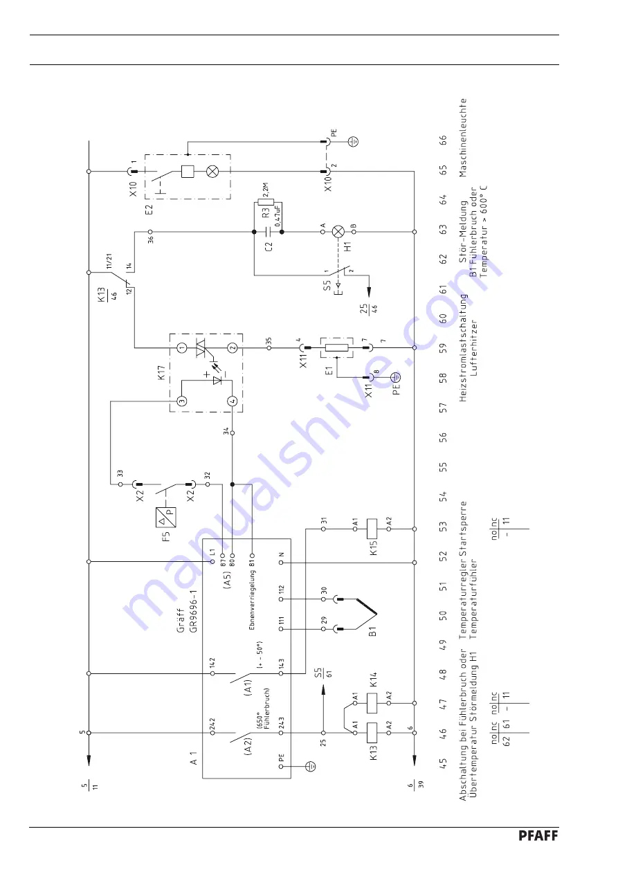
Страница 50: ...13 5 Circuit diagram general plan Version 28 03 01 91 211 718 95 Part 4 From the library of Diamond Needle Corp...

Страница 51: ...13 6 91 211 718 95 Part 5 Version 28 03 01 Circuit diagram general plan From the library of Diamond Needle Corp...

Страница 52: ...67653 Kaiserslautern K nigstr 154 D 67655 Kaiserslautern Telefon 0631 200 0 Telefax 0631 17202 E Mail info pfaff industrial com Gedruckt in der BRD Printed in Germany Imprim en R F A Impreso en la R...

Отзывы: