Pfaff 3586-22/02 Скачать руководство пользователя страница 65


Input


65


Confi rm the input.


Call up function 

and enter value "20" for the dart depth on the number block.


Confi rm the input.

The values for the curvature (functions 

and 

5) 

remain unchanged.


Call up function 

and enter value "20" for the waist depth on the number block.


Confi rm the input.


Call up function 

and enter value "57" for the waist length on the number block.


Confi rm the input.


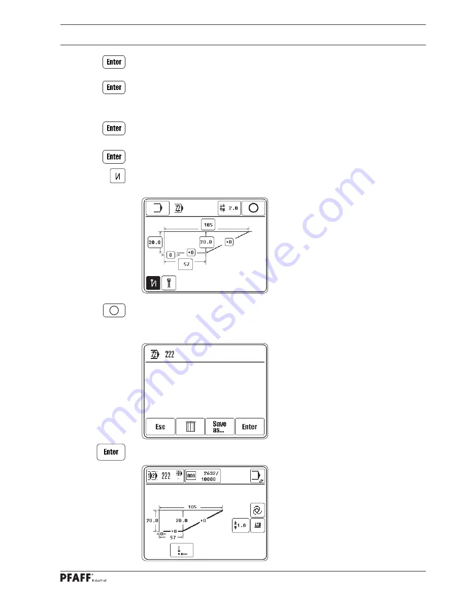
Activate the start backtack.


Conclude the seam program input.

The values are checked and the seam construction diagram is calculated. If errors are 

detected, these are displayed with a corresponding message.


Save the seam program.

Содержание 3586-22/02

Страница 1: ...96 12 19 375 002 Instruction Manual engl 07 18 This instruction manual applies to machines from the serial number 2 812 160 and software version 0382 020 0383 020 0433 006 0433 020 onwards 3586 22 02...

Страница 2: ...in chapter 3 Technical Data Reprinting copying and translation including excerpts from PFAFF instruction books is permitted only with our prior approval and listing of sources PFAFF Industriesysteme u...

Страница 3: ...ting Controls 17 7 01 Main switch 17 7 02 Bundle clamp switch option 17 7 03 Control panel 18 7 04 Loading table switch only on the Pfaff 3586 24 02 and 25 19 7 05 Blower switch only on the Pfaff 3586...

Страница 4: ...tering seam programs 53 11 02 01 Creating altering single point darts 1 55 11 02 02 Creating altering single point darts 2 56 11 02 03 Creating altering a waist pleat 1 57 11 02 04 Creating altering a...

Страница 5: ...103 13 08 06 Manual cutting control 104 13 08 07 Control cam recalibrating 105 13 09 Adjusting the feed mechanisms 106 13 09 01 Aligning the workholder bar 106 13 09 02 Aligning the X axis drive unit...

Страница 6: ...ramming 137 14 02 05 SD card errors 138 14 02 06 Sewing motor errors 138 14 02 07 Stepping motor drive errors 139 14 03 List of inputs and outputs 140 14 03 01 CAN node 1 140 14 03 02 Special outputs...

Страница 7: ...hine from the electricity mains when leaving the workplace and performing maintenance by operating the main switch or removing the mains plug The daily maintenance work may only be carried out by suit...

Страница 8: ...tor This instruction manual is a part of the machine and must be made available to the operating personnel at all times The instruction manual must have been read before the initial start up The opera...

Страница 9: ...impair its safety must be reported to the owner operator immediately 1 05 02 Technical staff Technical staff are persons with technical training in electricity electronics and mechanics They are respo...

Страница 10: ...ver Do not operate the machine without the belt guard 2 Risk of injury due to moving parts Do not reach under the needle strip 3 Danger of crushing when the needle strip 3 is lowered Do not reach unde...

Страница 11: ...arts and waist pleats with and without a basting seam Any usage not approved by the manufacturer is deemed misuse The manufacturer shall assume no liability for damage caused by misuse Proper use also...

Страница 12: ...th 37 mm 3586 23 01 23 02 24 02 25 3 20 mm Waist pleat length 3586 22 02 to 250 mm 3586 23 01 23 02 to 290 mm 3586 24 02 25 to 490 mm Waist pleat depth 3586 22 02 23 01 3 70 mm 3586 23 02 22 mm 3586 2...

Страница 13: ...586 24 02 25 1240 mm Height without reel stand 3586 22 02 23 01 23 02 1040 1420 mm 3586 24 02 25 1210 1480 mm Weight 3586 22 02 23 01 23 02 200 kg 3586 24 02 25 270 kg Subject to alterations Due to th...

Страница 14: ...rious plastics The electrical equipment consists of plastics and copper The machine must be disposed of in accordance with the locally valid environmental protection regulations with a specialised com...

Страница 15: ...e ensure that the machines are only transported in a vertical position 5 03 Disposal of the packaging materials The packaging materials of these machines consist of paper cardboard and VCI fleece It i...

Страница 16: ...med or important information in this instruction manual are emphasised by symbols The symbols used have the following meaning Note information Cleaning care Lubrication Maintenance repairs adjustment...

Страница 17: ...in switch Turning the main switch 1 switches the machine power supply on and off Fig 7 01 1 7 02 Bundle clamp switch option The switch 1 is used to open and close the bundle clamp The bundle clamp doe...

Страница 18: ...by pressing on the respective point on the monitor Pressing the respective function causes its immediate actuation or activation deactivation or another menu will appear e g for inputting a value Acti...

Страница 19: ...1 is only required if necessary to make it easier to slide back the loading table Activating the switch 1 vents the loading table quickly and makes it easy to slide back Fig 7 04 1 7 05 Blower switch...

Страница 20: ...0 Fig 7 06 1 7 06 Pedal only on the Pfaff 3586 25 Pressing the pedal 1 1x turns the suction on 2x turns the suction off Pressing the pedal 2 moves the loading table forward if the suction is switched...

Страница 21: ...p Suitable electrical supply connections must be provided at the erection site see chapter 3 Technical Data The erection site must also have a firm and level subsurface and adequate lighting The table...

Страница 22: ...nus keys Assemble the reel stand as shown in the adjacent image Fig 8 02 8 01 03 Mounting the bundle clamp option Insert the bundle clamp into the guide 2 with the square head screw 1 Tighten the scre...

Страница 23: ...oses for possible damage Arrange for technical staff to check whether the machine may be operated at the existing mains voltage and whether it is connected properly Do not operate the machine if there...

Страница 24: ...ng the machine off Turn the main switch 3 to position 0 to switch off the machine Description of further functions on the display Input menu This function is used to call up input mode see chapter 11...

Страница 25: ...Set up and Initial Start up 25 8 04 Selecting the language Switch the machine on Call up the input menu Call up the Country settings menu Select the language accordingly...

Страница 26: ...ch the machine on Call up Input mode Call up the service menu Call up the control panel functions Change the display contrast Switch the key tone off or on Never reduce the display contrast to such an...

Страница 27: ...the piston rod of the X drive must rest in the corresponding openings of the adjustment gauge 2 2 The adjustment pin 1 must plunge into the corresponding hole in the adjustment gauge 2 when turning t...

Страница 28: ...2 Mount the workholder bar and sewing foot Call up the Carriage position function Remove the workholder bar and sewing foot and move to the carriage position Remove the needle insert the adjustment p...

Страница 29: ...ting the zero point of the material take over unit Rule The extended needle bar 1 should be parallel to the workholder bar 2 with a clearance of 3 mm 1 2 Fig 8 08 Call up the menu to set the zero poin...

Страница 30: ...rding to the rule and press Enter to accept the setting 8 08 Adjusting the starting point correction Rule 1 The first stitch should lie securely in the workpiece in seams without a start backtack 2 Th...

Страница 31: ...to home position the machine is ready for operation Check that the needle is positioned at t d c Adjust the needle position if necessary using the Needle position function see chapter 13 10 Sewing mo...

Страница 32: ...table 1 Switch off the machine and secure it against reactivation Risk of injury if the machine suddenly starts up It is essential that the sealing ring 3 black on the vacuum valve 4 is replaced with...

Страница 33: ...art the sewing process or Move the machine to home position 9 Set up Observe and comply with all regulations and instructions in this instruction manual Pay particular attention to all safety regulati...

Страница 34: ...ng aid function The workholder bar moves out of the needle area the sewing foot is lowered and the sewing start is disengaged Thread the needle thread as shown in Fig 9 02 Please ensure that the needl...

Страница 35: ...uring sewing If the machine is only run for bobbin winding without sewing a bobbin case must be fitted in the hook Otherwise a jammed thread may damage the hook The tension of the thread on the bobbin...

Страница 36: ...ether with the bobbin Insert the filled bobbin in the bobbin case 3 so that the bobbin turns in the direction of the arrow when taking up the thread Pass the thread through the slot under the spring a...

Страница 37: ...t is set correctly if the sewing foot is positioned floats just above the sewing material Loosen the lock nut 1 and turn the knurled thumb screw 2 to adjust the sewing foot 3 according to the thicknes...

Страница 38: ...e selection and leave the selection menu Description of further functions Clear This function sets the value to 0 Arrow keys These functions increase or decrease the value Esc This function cancels th...

Страница 39: ...o input the program number Call up the menu to input the sequence Select the desired sequence number using the number block 0 9 Confirm the selection and leave the selection menu Description of furthe...

Страница 40: ...m the existing seam programs by entering the program numbers on the number block The cursor in the window shows which seam program is removed from the sequence or at which point a new seam program is...

Страница 41: ...stops automatically for bobbin changeover on reaching the number of bobbin thread stitches Description of further functions Clear on the number block This function sets the input value to 0 Arrow keys...

Страница 42: ...Set up 42...

Страница 43: ...e production are shown here on the display depending on the program selection and the machine status The machine normally works in automatic mode but it can be switched to manual mode to set up and te...

Страница 44: ...m number Bobbin thread stitch counter This function opens the menu for inputting and resetting the bobbin thread stitches see chapter 9 08 Setting the bobbin thread stitch counter Input menu This func...

Страница 45: ...mber see chapter 9 06 Selecting a program number Call up manual sewing Insert the sewing material Slide in the loading table The values of the seam construction diagram and first backtacks or starting...

Страница 46: ...to start the sewing sequence Home position These functions are used to move the machine to home position Move through the cycle This function is used to move through the cycle to the seam constructio...

Страница 47: ...s function is used to stop the sewing sequence If the intermediate stop is activated with parameter 107 an intermediate stop is made in the program sequence The corresponding functions can be used to...

Страница 48: ...rams The function depends on the setting of parameter 114 Automatic sequencing see chapter 13 11 02 List of parameters This function is used to inversely show the next individual program to be machine...

Страница 49: ...u to change the material thickness Home position These functions are used to move the machine to home position 10 04 Program interrupt The program sequence can be interrupted by pressing the stop func...

Страница 50: ...ccurs when switching an output the relevant output is displayed with the desired switching state 0 or I 0 means that the output should be switched off and I means that the output should be switched on...

Страница 51: ...ment Parameter settings This function is used to call up the menu for changing parameter settings see chapter 13 11 Parameter settings 11 Input Input mode contains the functions for displaying informa...

Страница 52: ...the language displayed on the control panel see chapter 8 04 Selecting the language Rights of access This function opens a menu to define the rights of access see chapter 11 05 Rights of access Steppi...

Страница 53: ...den sation selecta ble selecta ble selecta ble selecta ble pre set selecta ble selecta ble End back tack selecta ble selecta ble pre set not possible not pos sible selecta ble selecta ble End stitch c...

Страница 54: ...03 Creating altering a waist pleat 1 Waist pleat 2 This function is used to call up the entry of a waist pleat see chapter 11 02 04 Creating altering a waist pleat 1 Basting seam This function is use...

Страница 55: ...his function is used to conclude the seam program input and the machine switches to sewing mode Dart length Function 1 is used to input the value for the dart length Dart depth Function 2 is used to i...

Страница 56: ...sewing mode Dart length Function 1 is used to input the value for the dart length Dart depth Function 2 is used to input the value for the dart depth Waist depth Function 3 is used to input the value...

Страница 57: ...am input and the machine switches to sewing mode Waist pleat length Function 1 is used to input the value for the waist pleat length Waist pleat depth Function 2 is used to input the value for the wai...

Страница 58: ...s function is used to activate the end stitch condensation Basting seam This function is used to attach a basting seam The basting seam depth corresponds to the hip depth of the waist pleat The start...

Страница 59: ...e machine switches to sewing mode Waist pleat length Function 1 is used to input the value for the waist pleat length Waist pleat depth Function 2 is used to input the value for the waist pleat depth...

Страница 60: ...ack This function is used to activate the end backtack End stitch condensation This function is used to activate the end stitch condensation Basting seam This function is used to attach a basting seam...

Страница 61: ...sed to call up the menu for inputting the stitch length Sewing This function is used to conclude the seam program input and the machine switches to sewing mode Basting seam length Function 1 is used t...

Страница 62: ...art length Dart depth Function 2 is used to input the value for the dart depth Curvature Functions 3 and 4 are used to input the values for the respective curvature Waist depth Function 5 is used to i...

Страница 63: ...s used to input the value for the dart depth Curvature Functions 3 and 4 are used to input the values for the respective curvature Waist depth Function 5 is used to input the value for the waist depth...

Страница 64: ...mm A start backtack should be performed at seam start Switch the machine on Call up Input mode Call up seam program input Call up the menu for machining a dart 2 Enter program number 222 on the number...

Страница 65: ...3 and enter value 20 for the waist depth on the number block Confirm the input Call up function 7 and enter value 57 for the waist length on the number block Confirm the input Activate the start back...

Страница 66: ...via the touch panel It is necessary to initially run through a newly created or altered seam program to ensure that no collision occurs Only standards seam types are preprogrammed Special configuratio...

Страница 67: ...Input 67 Call up seam program input Call up teach in Enter the program number e g 20 on the number block Confirm the input...

Страница 68: ...t 68 Slide in the table Confirm Move through the cycle 1x key Use the keys to input the insertion depth e g 15 0 Confirm Move through the cycle 1x key Confirm the key until the programming window appe...

Страница 69: ...Confirm Move forward through cycle 1x Call up Creating altering seam program input Use the arrow keys to move the X Y points e g X 100 Y 105 Press the key 1x to confirm the entry Call up the Insert f...

Страница 70: ...Input 70 Call up the Sew on function Call up the Stitch length function Enter the value for the stitch length e g 1 50 mm Confirm the input Call up the Straight seam function to insert a straight seam...

Страница 71: ...Input 71 Use the arrow keys to move the X Y points e g X 400 Y 10 Press the key 1x to confirm the entry End the straight seam input Call up the Insert function Call up the Stitch length function...

Страница 72: ...e stitch length e g 1 70 mm Confirm the input Call up the Straight seam function to insert a straight seam Use the arrow keys to move the X Y points e g X 800 Y 105 Press the key 1x to confirm the ent...

Страница 73: ...put function in status bar Press Enter to save the input Move to home position Call up program 20 see chapter 9 06 Selecting a program number It is necessary to initially run through a newly created o...

Страница 74: ...piece counter Operating hours counter Production hours counter The daily piece counter can be reset with the Clear function Country settings This functions opens a menu to select the language displaye...

Страница 75: ...the home position or in the seam at sewing stop Insert The function is used to insert functions and blocks Delete This function is used to delete the current section Conclude the input This function i...

Страница 76: ...the circular arc Sew on This function is used to start the sewing All subsequent sections are sewn until the Thread trimming function is selected or Thread trimming The thread is trimmed The Sew on f...

Страница 77: ...rs with the corresponding files appear on the display Machine memory C DATA is currently selected SD card is currently inserted The data carrier is selected by touching the appropriate box The content...

Страница 78: ...ination with the lock key Copy This function is used to copy the files selected from the current data carrier to the second data carrier Delete This function is used to delete the selected files MDAT...

Страница 79: ...e so called super user who has a key switch to access all functions and who is authorised to stipulate the rights of access Enter the key switch and switch on the machine Call up Input mode Call up th...

Страница 80: ...nter 2 Input 3 Create new program 4 Program management 5 Parameter settings 6 Info 7 Reset daily piece counter 8 Delete operating hours counter 9 Delete production hours counter 10 Country settings 11...

Страница 81: ...lean the hook area daily several times if in continuous operation Clean the needle area several times a day Check oil level daily before start up Lubricate the bevel gears once as year Clean the blowe...

Страница 82: ...e only be determined on a case by case basis Disconnect the machine from the electricity mains for all cleaning work by shutting off the main switch or removing the mains plug Risk of injury due to ac...

Страница 83: ...rom the electricity mains for all cleaning work by shutting off the main switch or removing the mains plug Risk of injury due to accidental machine start up Open the hook area cover 1 Clean the hook 2...

Страница 84: ...nit has been removed Cleaning the filter Unscrew the water tank 1 and take out the filter 2 Clean the filter 2 with compressed air or isopropyl alcohol order no 95 665 735 91 Screw in the filter 2 and...

Страница 85: ...r pressure on the manometer 1 before every start up The manometer 1 must show a pressure of 6 bar Adjust this value if needed To do this pull up the button 2 and turn it so that the manometer 1 shows...

Страница 86: ...t always have oil in it Danger of machine damage Check the oil level daily add oil through the hole 3 as needed up to the line as a maximum The oil tank 4 serves solely for topping up the oil reservoi...

Страница 87: ...injury if the machine suddenly starts up Only use Isoflex Topas L32 high performance grease order no 280 1 120 210 Remove the cover of the X feed If necessary use a grease gun to lubricate the guides...

Страница 88: ...e and secure it against reactivation Risk of injury if the machine suddenly starts up Remove the union 1 Remove the filter ring 2 and clean with the compressed air gun Fit the filter ring 2 Tighten th...

Страница 89: ...at have to be completely adjusted Both the preceding and following chapters must be observed if only specific individual work steps are carried out The screws and nuts indicated in brackets are fasten...

Страница 90: ...ainst reactivation Risk of injury due to accidental machine start up Slide the workholder bar 1 to the left and fold it out Tilt the material take over unit 2 backwards screws 3 two screws in total Sl...

Страница 91: ...dle bar in the needle rise position needle bar is positioned 1 8 mm after b d c Turn the handwheel until the needle bar is approximately in the required position Fit the adjustment gauge 1 as shown in...

Страница 92: ...ar is positioned 1 8 mm after b d c Move the needle bar to a position 1 8 mm after b d c see chapter 13 05 Checking and adjustment aid Turn the toothed belt wheel 1 according to the rule and slide on...

Страница 93: ...hole Loosen the screws 1 2 and 3 Adjust the needle bar frame 4 according to the rule Tighten the screw 2 and gently tighten the screw 3 Use the screw 1 to pull the internal guide pin up to the eye of...

Страница 94: ...hould be minimal yet noticeable play between the plastic pinion 3 and the steel wheel 4 This play should be approximately the same for a 360 turn 3 The steel wheel 4 should align with the plastic pini...

Страница 95: ...held over the needle plate cutout after approximatelya 10 seconds when the machine is running at full speed The setting is only required if the wick is replaced Make sure that the new wick is impregna...

Страница 96: ...of the needle should be 0 8 mm under the hook point 3 There should be a clearance of 0 5 mm between the lug of the bobbin case position finger 4 and the base of the stop groove Move the needle bar to...

Страница 97: ...hould have moved approx 1 mm when forming the maximum thread loop while passing the thread around the hook Turn the thread tension 1 screw 2 according to rule 1 Adjust the slack thread regulator 3 scr...

Страница 98: ...way from the edge of the bobbin 3 The eccentric stud 6 should be at the centre of the large bobbin chamber Unscrew the drive unit 1 for the Y axis screws 2 Adjust the drive wheel 3 screws 4 according...

Страница 99: ...the thread trimmer 13 08 01 Pre adjusting the control cam Rule When the needle bar is at t d c the surface 1 of the control cam should be parallel to the bed plate Turn the control cam screws 2 accord...

Страница 100: ...extended the roller or the roller lever 4 should be a distance of 0 1 mm from the highest point of the control cam 5 2 The cylinder 3 should be parallel to the front edge of the bed plate Turn or adju...

Страница 101: ...ition as it moves Disconnect the thread trimmer from the pneumatic supplies and dismantle the needle plate Remove the knife 1 screw 2 not on the 25 01 Move the needle bar to b d c Loosen the stop 3 sc...

Страница 102: ...ht edge of the thread catcher see arrow Move the needle bar to b d c Slide the knife 1 under the locking tab and align according to rule 1 Gently tighten the screw 2 Manually adjust the thread catcher...

Страница 103: ...ing point the rear edge of the thread catcher cutout should be 1 mm 1 2 mm on the 25 01 in front of the bobbin case position finger 6 Swivel the roller lever 1 to the lowest point of the control cam 2...

Страница 104: ...he cutting operation manually If the threads are not cut according to the rule align the thread catcher 1 screws 2 to the knife 3 accordingly not on the 25 01 If the threads are not cut according to t...

Страница 105: ...tip of the thread catcher 6 and the centre of the lug Move the needle bar to b d c Manually press the roller lever 1 onto the control cam 2 and turn the handwheel until there is a clearance of 2 mm 3...

Страница 106: ...and the workholder bar when the workholder bar 1 right final position is in home position Align the workholder bar 1 screw 2 and nut 3 according to rule 1 Place the sewing material under the workhold...

Страница 107: ...4 mm Fig 13 18 13 09 02 Aligning the X axis drive unit Rule The lower edge of the guide rail 3 should stand parallel below the table top without the cover plate with a clearance of 64 mm Align the dri...

Страница 108: ...should be checked with the measuring device 2 Adjust the tensioning roller 1 lock nut accessible from the rear according to the rule For information regarding the proper handling of the measuring devi...

Страница 109: ...Adjustment 109 13 09 04 Stop on the Y axis drive unit Rule The workholder bar 3 must not strike against the sewing foot 4 Adjust the stop 1 screws 2 according to the rule 2 2 4 3 1 2 2 Fig 13 20 4 3...

Страница 110: ...ay on the Y axis drive unit Rule There should be no noticeable play in the Y axis drive unit when the machine is switched on Move the motor 1 screws 2 four screws in total towards the machine housing...

Страница 111: ...ioned 0 5 mm above the cover plate when the needle bar is lowered Switch the machine on Call up the input menu Call up the service menu Select the output OUT4 and lower the material take over unit Adj...

Страница 112: ...e retracted loading table 3 should be positioned in the middle of the cutout of the material take over unit 4 and parallel to the material take over unit 4 and the cover plate Adjust the guide 1 screw...

Страница 113: ...above the table top with a clearance of 1 5 mm when the sewing foot 1 is lowered 2 The needle 4 should be positioned centrally in the cutout of the sewing foot 1 Adjust the sewing foot 1 screws 2 acc...

Страница 114: ...height of the knife 1 so that the knife holder 8 does not grind on the cover plate 4 The clearance should be approx 1 5 mm Tighten the screws 6 The speed of the slow starting stitches must be adjusted...

Страница 115: ...thread suction only on the PFAFF 3586 25 The clearance to the suction 1 should be set so that it does not collide with the clamp 3 when the workholder bar 2 is moved The suction time should be set to...

Страница 116: ...e the input This function is used to conclude the input and the machine switches to sewing mode CAN nodes This function is used to select the CAN node the selected CAN node is shown inversely Special...

Страница 117: ...when performing a cold start The machine memory is deleted or reset to the factory setting Switch on the machine and call up input mode Call up the service menu Call up cold start Confirm Perform a co...

Страница 118: ...panel when the machine is switched on in order to load the operating program All data in the machine memory is deleted when the operating program is loaded Switch on the machine and press the FORCE U...

Страница 119: ...This function is used to increase or decrease the nominal speed Start The function starts the sewing motor Stop The function stops the sewing motor Thread trimming cycle This function is used to perfo...

Страница 120: ...arameter selection as well as changing the values is described below 13 12 01 Selecting and changing parameters Switch on the machine and call up the input menu Call up parameter input Select paramete...

Страница 121: ...ages when threading 0 off 1 on 0 1 1 107 Intermediate stop 0 off 1 intermediate stop for every program 2 intermediate stop on for program numbers 90 in every program group 0 2 0 108 Continuous run tes...

Страница 122: ...at which the pulse for the thread trim ming is given to the thread trimming valve is changed degrees after t d c needle bar 160 360 200 304 Reverse rotation position 0 Cover thread car ried position t...

Страница 123: ...ant range of 180 Needle in t d c 0 The command to start the carriage is issued when the needle penetrates the material but it only starts one half turn later 180 when the needle lifts out The stitch p...

Страница 124: ...storage spar 2 with screws 1 The height of the bracket 3 is readjusted with screws 4 With the switching valve 5 the clip 3 for removing the material opened or disabled 5 1 is closed and 5 2 is open B...

Страница 125: ...ontrol panel F2 500 mA T H5 24 V DC I O F3 2 5 A T H2 80 V DC stepping motor F4 6 3 A T H3 24V DC stepping motor F5 500 mA T H4 Pin assignment X 1 Secondary transformer PIN Signal PIN Signal 3 V1 18 V...

Страница 126: ...8 V AC 9 POWERF 10 V1 18 V X 3 Blower X4 X5 X6 PIN Signal PIN Signal 1 24 V I O 2 GND 24 V X 7 SM end phase PIN Signal PIN Signal 1 24 V SM 4 GND 24 V SM 2 80 V SM 5 GND 80 V SM 3 80 V SM 6 GND 80 V S...

Страница 127: ...unit 127 14 01 02 Basic control unit A20 Pin assignment X103 COM1 X101 COM2 PIN Signal PIN Signal 1Vterm1 6 2RxD 7 RTS 3TxD 8 CTS 4 9 Vterm2 5GND Supply Flat cable floppy PC 104 floppy Boot stop Suppl...

Страница 128: ...Vex 6 7 Inp2 14 Inp2 8 Inp1 15 Inp1 X208 CAN bus PIN Signal PIN Signal 1 P8HA 6 2 P8HA 7 3 DoRi 8 DoRi 4 GND 9 GND 5 X400 Main drive PIN Signal PIN Signal 1 Shielding 14 A_A 2 TxD_A 15 A_B 3 RxD_A 16...

Страница 129: ...tions and fuses are not provided Please refer to chapter 14 02 02 Sewing motor errors when error messages appear on the machine display Pin assignment X2 Synchroniser PIN Signal PIN Signal 1 KA 6 2 KB...

Страница 130: ...102 91 001 Please refer to chapter 14 02 05 Stepping motor drive errors for the LED sta tus indicators Pin assignment X5 Bootstrap PIN Signal PIN Signal 1 GND 2 BOOTSTRAP 3 RESIN 4 n c 5 TxD 6 RxD 7 1...

Страница 131: ...onnection of motor 1 to 3 PIN Signal 1 Winding 1 2 Winding 1 3 Winding 2 4 Winding 2 14 01 05 CAN node A10 The CAN node has the following basic setting Address S200 1 Pin assignment X300 Outputs PIN S...

Страница 132: ...4 V 7 IN5 25 GND 43 24 V 8 IN6 26 GND 44 24 V 9 IN7 27 GND 45 24 V 10 IN8 28 GND 46 24 V 11 IN9 29 GND 47 24 V 12 IN10 30 GND 48 24 V 13 IN11 31 GND 49 24 V 14 IN12 32 GND 50 24 V 15 IN13 33 GND 51 24...

Страница 133: ...OPERATING SOFTWARE COLD START CARRIED OUT New operating software Cold start COLD START CARRIED OUT Cold start Cold start ERROR 101 C167 error Switch off error ERROR 102 Node no status CAN error statu...

Страница 134: ...n invalid Troubleshoot ERROR 308 Needle zero point invalid Troubleshoot ERROR 309 Machine not in home position Troubleshoot ERROR 310 File not on source Troubleshoot ERROR 311 Source read error file c...

Страница 135: ...ot ERROR 347 Program number Seam over fold curve too large Troubleshoot ERROR 348 Program number Shorter basting seam length 50mm Troubleshoot ERROR 349 Program number Basting seam too short Troublesh...

Страница 136: ...x Switch off error ERROR 502 No ready signal from the control panel Switch off error 14 02 02 CAN errors Error byte Description bit7 End phase error short circuit bit6 bit5 bit4 Receive status wait fo...

Страница 137: ...itch length specification 13 No coordinate section before Bezier curve 14 Sewing area limit exceeded 15 Curve without end point 16 Machine function buffer overflow 17 Sewing command in loading point p...

Страница 138: ...chine speed 58 Incorrect position 59 Path for guided positioning too low 60 No reset of the position counter possible motor running 61 Turning to t d c after power on not permitted 62 System mark not...

Страница 139: ...dy H 4 red Excess current on motor 1 Display Description 84 Power electronics fault during operation 85 No increments 86 Motor blocked 87 Commutation transmitter plug missing 88 Incremental transmitte...

Страница 140: ...knife on top OUT13 OUT2 Y15 Programmable output 2 25 01 option workholder bar thread clamp OUT14 OUT15 Y12 Loading table slowly forward Y8 blowing is then eliminated Valve OUT16 Y13 Stacking arm forwa...

Страница 141: ...ading table depressurised S2 Loading table slowly back S3 Air blast function S4 Fabric blowdown function test in 24 02 14 04 Boot key This work must only be per formed by trained technical staff Do no...

Страница 142: ...pneumatic diagram is drawn in the machine s home position The power air and electric ity is connected The components are in a fixed state Pneumatic circuit diagram Version 29 03 03 95 779 287 95 Part...

Страница 143: ...143 95 779 287 95 Part 2 Version 22 08 01 Pneumatic circuit diagram Thread cutter Blowing Blowing Material clamp Bundle clamp Option...

Страница 144: ...t 1 Loading table Suction Thread tension Needle strip Workholder bar Sewing foot Air curtain 15 02 PFAFF 3586 23 01 23 02 The pneumatic diagram is drawn in the machine s home position The power air an...

Страница 145: ...145 95 779 349 95 Part 2 Version 03 07 06 Pneumatic circuit diagram Thread cutter Air blast sewing foot Bundle clamp Option only on the 23 01 Option...

Страница 146: ...nents are in a fixed state PK4 8 7 B1 3 B1 1 1 2 3 1 3 Y X A 4 2 3 1 5 4 2 3 1 5 4 2 3 1 5 B 5 16 1 PK3 9 10 PK4 4 2 3 1 5 4 2 3 1 5 4 2 3 1 5 4 2 3 1 5 Ventilblock 99 137 459 91 1 Zuf hrtisch 2 bar m...

Страница 147: ...147 95 779 425 95 Part 2 Version 28 04 17 Pneumatic circuit diagram 4 2 3 1 5 7 Fadenschneiden 3 PK3 Y7 out 8 0 Optionen Materialklemme am Zuf hrtisch 9 12 PK3 10 B ndelklammer PK4 14 15...

Страница 148: ...3 1 5 Ventilblock valve block 99 137 459 91 1 Zuf hrtisch Loading table 2 bar max Y1 2 out 2 0 Y1 1 out 1 0 Saugen an Tischplatte und Zuf hrtisch Sucking on table board and loading table 2 Y2 out 3 0...

Страница 149: ...adenklemme der Druckleiste thread clamp of pressure bar 19 20 Fadenrestabsaugung thread ends sucktion PK 3 PK 6 PK 6 24 22 Ventil Einheit valve unit 5 1 3 2 4 2 3 1 1 2 4 5 2 4 3 1 5 2 3 1 1 2 2 1 3 A...

Страница 150: ...rail detection attached F1 F2 Fuse 6 3x32 10A T M1 Stepping motor X M2 Stepping motor Y M3 Stepping motor T M4 Sewing motor Ministop MS2 QE 3760 Q1 Main switch SMXNULL Initiator zero position on step...

Страница 151: ...1 M4 L1 T1 W chter O Faden F W 5 6 6 5 XW1 X7 X61 T2 SM Ends SM 2 M2 X8 X Achse Y Achse L2 U 3 4 X61 A20 A30 A22 A40 Z1 Q1 M4 M1 M2 M3 SM 3 M3 X9 Z Achse OPTION X30 W V U M 3 5 3 1 6 4 2 230V 6A Vakuu...

Страница 152: ...2 3 4 6 5 7 8 9 10 11 15 13 12 14 1 2 4 3 5 6 7 8 9 13 10 11 12 14 15 2 4 3 5 6 7 8 9 13 10 11 12 14 15 1 1 2 3 4 6 5 7 8 9 10 11 15 13 12 14 X200 A10 24V 80V 80V GND 24V GND 80V GND 80V Puls Richtung...

Страница 153: ...RXD TXD A OC B OC I OC 1 PE 6 7 8 9 10 11 12 13 14 15 16 17 18 19 20 GND REF1 REF1 REF2 REF2 GND A A B B INDEX INDEX GND 21 22 23 24 25 1 5 9 2 3 4 6 8 7 3 N S PE U V W 1 2 PE X1 Power X1 X2 X14 X6 G...

Страница 154: ...GND 12 30 GND 13 31 GND 14 32 GND 15 33 GND 16 34 GND X300 X4 X300 18 36 1 2 24V GND 24V GND X208 X200 1 2 3 4 5 6 7 8 9 OUT 1 OUT 4 OUT 3 OUT 6 OUT 5 OUT 8 OUT 7 OUT 10 OUT 9 OUT 12 OUT 11 OUT 14 OUT...

Страница 155: ...9 13 31 IN 11 GND 24V SMXLIMIT 50 14 32 IN 12 GND 24V E10 51 15 33 IN 13 GND 24V 52 16 34 IN 14 GND 24V 53 17 35 IN 15 GND 24V 54 18 36 IN 16 GND 24V X21 X20 X22 X400 A20 X401 4 3 1 2 X4 X300 17 36 1...

Страница 156: ...X101 X106 X108 X103 X110 X42 X41 X40 1 2 3 4 5 6 7 8 9 10 1 2 3 4 5 30 31 32 33 34 2 1 3 4 5 6 7 8 9 10 1 2 6 5 4 3 9 8 7 1 2 RS232 Schnittstelle RxD TxD 0V RTS CTS 0V RxD TxD 0V RTS CTS 0V 24V 5V 0V...

Страница 157: ...Notizen...

Страница 158: ...an authorized licensee of the PFAFF trademark PFAFF Industriesysteme und Maschinen GmbH Hans Geiger Str 12 IG Nord D 67661 Kaiserslautern Telefon 49 6301 3205 0 Telefax 49 6301 3205 1386 E mail info p...

Отзывы: