background image

136

137

EN

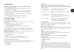
Function check/maintenance of the system separator

Installation and maintenance instructions for refilling combination

The maintenance of system separators may only be done by authorised technical personnel

• 

Inspection interval: every 6 months

• 

The maintenance check is to be carried out once per year

• 

Execution by an installation company

Installation

The fitting must be installed horizontally (according to the arrow direction).

Drain facing downwards. Flush the pipe before installation.

Application

This refilling combination is suitable for the filling and refilling of heating systems.

The integrated filling assembly automates the heating system filling procedure. Two non-re-

turn valves and a pressure reducer are integrated in the filling assembly; the pressure reduc-

er ensures that the filling pressure of the system is correct.

Thanks to the BA system separator, which operates according to the three-chamber princi-

ple, this compact fitting prevents the back suction, backflow or back pressing of non-drinking 

water from the heating system into the drinking water pipe.

Maintenance according to  EN 806-5

Unscrew the cap of the filling assembly, remove the cartridge, check it and if necessary 

replace it.

The system separator must be inspected and serviced at least once per year according to 

EN 12729.
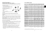
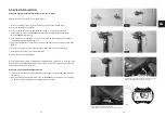
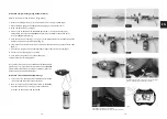
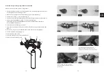
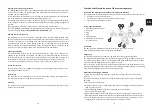
a. Close input (1) and output (1)
b. With the mini ball valves (2) in the closed state, remove the plug (4) and connect the input 

tube of the test kit there

c. Remove the plug (3) and connect the output tube of the test kit there.

Open the mini ball valves again

d. Slowly open the bypass valve of the test kit until the drain valve begins to drip; note the 

differential pressure. With the first droplet, the differential pressure must be over 0.14 bar.

e. Close the bypass valve again; the pressure increases to 0.4 bar (preset pressure); the car-

tridge begins to work again: the system separator is working correctly.

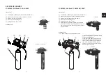
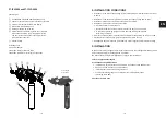
System separator type BA

1.  Maintenance shut-off valves

2.  Test valves

3.  Plug

4.  Plug

5.  Filling assembly

6.  Manometer with manome-

ter connection ¼"

2

3

5

1

6

4

2

1

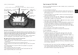
Refilling water monitoring/limitation
This setting defines the maximum permitted quantity of refilling water per week. In the case 

of the PT-FCS / PT-FCSD, the acoustic signal and relay output are activated if the set value is 

reached. The set value pulsates.

In the case of the mains variants PT-FCS / PT-FCSD, the supply of refilling water is interrupted 

as well by closing the solenoid valve and the display lights up red.

By pressing OK, the water quantity is reset again, the signal is deactivated and the solenoid 

valve is opened for 20 or 75 minutes (PT-FCS) respectively. The display lighting changes back 

to white.

Setting range: 10 – 190 l/7d in steps of 10 l/7d or deactivated.


Display shows (---).

The refilling quantity monitoring must be deactivated when filling for the first time (see point 

7. Commissioning). Factory setting deactivated. Display shows (--).

Refilling interval (PT-FCS only)
The refilling unit in the PT-FCS version is equipped with a normally closed solenoid valve 

(NC). The solenoid valve opens after an adjustable interval of 48, 96 or 192 hours for 20 or 

75 minutes respectively, so that filling water can automatically be added if necessary. It is 

recommended to leave the factory setting of 192 hours unchanged in order to guarantee 

the best possible volumetric measurement of the refilling water. Shorter intervals may be 

necessary in the case of larger systems or a high refilling water requirement.

Conductance display
The conductance display (0 – 99 µS/cm) is only updated when a flow rate is measured. De-

pending on the permasoft size entered, the update only takes place between 0.3 and 1.5 

litres in order to take into account the counterion effect of the mixed bed cartridge. At a 

conductance of > 40 µS/cm, the colour of the display changes to red (PT-FCS/PT-FCSD).

In the case of a defective conductance sensor or a short-circuit, the display shows "E1".

Total water counter
The total water counter (1 to 99999 litres) registers the total filling water quantity since com-

missioning and cannot be reset.

Data storage
The  set  values  of  the  parameters  are  saved  one  second  after  leaving  the  settings  menu. 

The total water quantity is saved once every 24 hours.

Cleaning
The electronics housing may only be cleaned with clean drinking water. All-purpose or glass 

cleaners are not suitable.

Содержание PT-DA-CH5000

Страница 1: ...van cv installatie Mode d emploi Stations de remplissage de chauffage Istruzioni per l uso Gruppi di rabbocco per impianti di riscaldamento Instruction manual digital heating filling station PT DA1000...

Страница 2: ...schluss Druckminderer Manometer batteriebetriebene Elektronik mit 4 Zoll Display Wasserz hler Leitwertmessung D mmschalen und permasoft Sie misst die Leitf higkeit des Nachspeise wassers berwacht die...

Страница 3: ...5000FD Separate ein und ausgangsseitige Absperrventile Elektronik mit beleuchtetem 4 Zoll Display Entl ftungshahn mit Sp lschlauch Halteb gel mit Schraubenset Systemtrenner nach DIN EN 1717 Typ BA mi...

Страница 4: ...Wassersch den sollte ein ausreichender Bodenablauf vorhanden sein 5 EINBAU Um das Volumen des Stagnationswassers so klein wie m glich zu halten ist die Nachf llkom bination m glichst direkt an die Ve...

Страница 5: ...h use aufstecken Abb 4 zuvor die Papierfahne am Batteriefach 2x Batterie AA entfernen Abb 8 5 Leitwertsensor II seitlich an der Elektronik einstecken beidseitig m glich Abb 6 und 7 6 Ggf Impulsleitung...

Страница 6: ...stecken Abb 4 zuvor bei PT DB die Papierfahne am Batteriefach 2x Batterie AA entfernen Abb 8 6 Leitwertsensor II seitlich an der Elektronik einstecken beidseitig m glich Abb 6 und 7 7 Ggf Impulsleitun...

Страница 7: ...unten einschrauben Abb 4 alternativ den Adapter PS AD28000 mit den flexiblen Anschlussschl uchen f r PT PS28000E mit der Armatur verbinden 6 Elektronikgeh use aufstecken Abb 5 7 Leitwertsensor II seit...

Страница 8: ...wird ausgel st wenn die rote LED aufleuchtet Elektrische Leitf higkeit ist zu hoch oder die berechnete Restkapazit t gleich Null ist bzw die max Nachspeisemenge pro Woche wird berschritten SIGNAL AUS...

Страница 9: ...gelventile bis zur n chsten Wartung zu schlie en Bei der permasoft Version PT PS1000FD darf der Volumenstrom bei der Nachspeisung maximal 2 l min betragen da sonst zunehmend Salze aus dem Trinkwasser...

Страница 10: ...elhahns 12 Bei einer Druckdifferenz von 0 3 bar zwischen eingestelltem Nachdruck und dem Druck in der Anlage wird nun entsalztes Wasser nachgespeist Im Display wird dabei der aktuelle Volumenstrom in...

Страница 11: ...beleuchtet werden 3 F r die Eingabe der Gr en muss die ESC Taste ca 3 Sek gedr ckt werden bis die Anzeige f r die Rohwasserleitf higkeit pulsiert 4 Eingabe der Rohwasserleitf higkeit von 100 1500 S c...

Страница 12: ...r Wert der Einstellparameter vergr ert rechte Pfeiltaste bzw verkleinert linke Pfeiltaste Wird eine Taste l nger als 1 Sek gedr ckt gehalten ver ndert sich der Wert mit zunehmender Geschwindigkeit OK...

Страница 13: ...stellwerte der Parameter werden eine Sekunde nach Verlassen des Einstellmen s gespeichert Bei der Gesamtwassermenge wird die Speicherung einmal in 24 Stunden vorgenommen Reinigung Die Reinigung des El...

Страница 14: ...CHE DATEN DE 11 ST RUNGEN ST RUNG URSACHE BEHEBUNG kein oder zu wenig Durchfluss Systemtrenner nicht in Durchflussrichtung montiert Systemtrenner in Durchflussrichtung montieren Pfeilrichtung auf Geh...

Страница 15: ...en wo sie unentgeltlich abgegeben werden k nnen WEEE Reg Nr DE 91509671 DE EG KONFORMIT TSERKL RUNG Hersteller perma trade Wassertechnik GmbH Anschrift R ntgenstra e 2 D 71229 Leonberg Produktbezeichn...

Страница 16: ...isplay watermeter ge leidingsmeting isolatieschalen en permasoft Ze meet de geleidbaarheid van het laatste toe voerwater controleert de capaciteit van de permasoft demineraliseringseenheid alsook de v...

Страница 17: ...00 Voedingseenheid 24 V PT DB1000 PT DB5000 Tip Gedemineraliseerd water is uitste kend geschikt als strijkwater Hiervoor afsluitklep aan ingangszijde naast systeemscheider openen afsluitklep aan uitga...

Страница 18: ...snel mogelijk op de toevoerleiding worden aangesloten Bij de montage gelden de regels van de tapwaterverordening 1 Buisleiding goed doorspoelen 2 Verwarmingsvulstation monteren Montage in horizontale...

Страница 19: ...ktronicabehuizing Afb 4 Verwijder de papieren vlag uit het batterijvak 2x AA batterij Afb 8 5 Inbrengen van de geleidingssensor II aan de zijde van de elektronica mogelijk aan beide zijden Afb 6 en 7...

Страница 20: ...zing Afb 4 Verwijder de papieren vlag uit het batterijvak PT DB 2x AA batterij Afb 8 6 Inbrengen van de geleidingssensor II aan de zijde van de elektronica mogelijk aan beide zijden Afb 6 en 7 7 Sluit...

Страница 21: ...itdop op de systeemscheider 3 Schroefkogelkranen aansluiten op installatie Afb 2 4 Schroefkogelkranen naar digitaal verwarmings vulstation Afb 3 5 permasoft PT PS5000FD van onderen inschroeven Afb 4 A...

Страница 22: ...INGEN VOOR SIGNAAL EN PULS UITGANG Het digitale verwarmingsvulstation kan via de signaaluitgang R voor relais in een gebou wbeheersysteem worden ge ntegreerd Voor versies met batterij PT DA und PT DB...

Страница 23: ...gelkleppen tot het volgende onderhoud te sluiten Bij de permasoft versie PT PS1000FD mag het debiet bij de latere toevoer maximaal 2 l min bedragen aangezien anders toenemend zouten uit het tapwater d...

Страница 24: ...ep 11 Openen van de kogelkraan aan de uitgangszijde 12 Bij een drukverschil van 0 3 bar tussen ingestelde nadruk en de druk in de installatie wordt nu ontzout water achteraf toegevoerd Op het display...

Страница 25: ...worden verlicht 3 Voor de invoer van de afmetingen moet gedurende 3 sec op de toets ESC worden gedrukt tot de weergave voor de geleidbaarheid van ongezuiverd water pulseert 4 Invoer van het geleidings...

Страница 26: ...t de pijltjestoetsen wordt de waarde van de instelparameter vergroot rechtse pijltjes toets resp verkleind linkse pijltjestoets Wordt een toets langer dan 1 sec ingedrukt ge houden dan verandert de wa...

Страница 27: ...e na het verlaten van het instelmenu opgeslagen Bij de totale waterhoeveelheid wordt de opslag eenmaal binnen de 24 uur uitgevoerd Reiniging De reiniging van de elektronische behuizing mag enkel met h...

Страница 28: ...richting gemonteerd Systeemscheider in doorstroomrichting monteren pijlrichting op behui zing letten Afsluitkogelkranen voor of na navulcombinatie niet volledig geopend Afsluitkogelkranen volledig ope...

Страница 29: ...afgevoerd met het afval waar ze gratis kunnen worden afgegeven WEEE Reg nr NL B 91509671 NL EG CONFORMITEITSVERKLARING Fabrikant perma trade Wassertechnik GmbH Adres R ntgenstra e 2 D 71229 Leonberg P...

Страница 30: ...n s parateur BA avec robinets de contr le et raccor dement pour les eaux us es d un d tendeur d un manom tre d lectronique Pile 3 V avec cran 4 pouces d un compteur d eau et d une mesure de la conduct...

Страница 31: ...sortie s par es lectronique avec cran 4 pouces clair Purgeur d air avec tuyau de rin age trier de blocage avec jeu de vis S parateur de syst me selon DIN EN 1717 type BA avec raccordement au conduit...

Страница 32: ...ge doit tre bien accessible simplifie la maintenance le manom tre sur le d tendeur peut bien tre observ Tron on de soulagement de 5 x DN pr vu derri re la combinaison d appoint selon DIN EN 806 Dans l...

Страница 33: ...ue Fig 4 d abord retirer l tiquette en papier sur le compartiment des piles 2 piles AA Fig 8 5 Ins rer le capteur de conductance II sur le c t de l lectronique possible des deux c t s Fig 6 et 7 6 Le...

Страница 34: ...tronique Fig 4 d abord retirer l tiquette en papier sur le compartiment des piles 2 piles AA Fig 8 6 Ins rer le capteur de conductance II sur le c t de l lectronique possible des deux c t s Fig 6 et 7...

Страница 35: ...asoft PT PS5000FD par le bas visser fig 4 alternativement l adaptateur PS AD28000 avec les tuyaux de raccordement flexibles pour PT PS28000E la robinetterie 6 Brancher le bo tier lectronique Fig 5 7 I...

Страница 36: ...nal est d clench lorsque la LED rouge s allume La conductivit lectrique est trop lev e ou la capacit r siduelle calcul e est gale z ro ou la quantit maximale de r ali mentation par semaine est d pass...

Страница 37: ...bit volum trique lors de la r alimentation ne doit pas d passer 2 l min sinon les sels de l eau potable passeront de plus en plus au travers Lors du premier remplissage avec le PT PS18000 ou le PT PS...

Страница 38: ...u sph rique du c t de la sortie 12 Pour une diff rence de pression 0 3 bar entre la pression r gl e en aval et la pression dans l installation on ajoute maintenant de l eau d min ralis e L cran affich...

Страница 39: ...LED rouge est active elle ne reste allum e que jusqu ce que la prochaine mesure de conductivit ait eu lieu Si la conductivit mesur e 40 S cm LED rouge l lectrovanne se referme imm diatement Lors du pr...

Страница 40: ...l ch es la valeur du param tre de r glage est grossie touche fl ch e droite ou r duite touche fl ch e gauche Si la pression sur une touche dure plus d 1 seconde la va leur se modifie avec une vitesse...

Страница 41: ...ance Limitation de l eau d appoint Ce r glage d finit la quantit maximale d eau d appoint autoris e par semaine Si la valeur param tr e est atteinte le signal acoustique et la sortie relais s activent...

Страница 42: ...SE LIMINATION aucun d bit ou d bit insuffisant le s parateur n est pas mont dans le sens du d bit monter le s parateur dans le sens du d bit respecter le sens de la fl che sur le bo tier robinets d ar...

Страница 43: ...__________________________ Cette d claration certifie la conformit avec les directives cit es ne contient toutefois aucune garantie de propri t s Dr D Ende Head of Research and Development Sous r serv...

Страница 44: ...o all acqua di scarico riduttore di pressione manometro sistema elettronico Batterie 3 V con display da 4 pollici contatore dell acqua e misurazione della conducibilit gusci isolanti e permasoft Quest...

Страница 45: ...te sul lato d ingresso e d uscita Sistema elettrico con display illuminato da 4 pollici Rubinetto di sfiato con tubo di lavaggio Staffa Disconnettore di sistema in conformit a EN 1717 tipo BA con alla...

Страница 46: ...cessibile facilita la manutenzione Il manometro sul riduttore di pressione pu essere ben osservato Prevedere un tratto di tubazione 5 x DN dietro al gruppo di reintegro in conformit a EN 806 In PT DBP...

Страница 47: ...llegamento per PT PS28000ILE con il gruppo 4 Collegare il display ill 4 rimuovere prima la targhetta di carta sul vano batterie 2x batteria AA ill 8 5 Inserire il sensore di conducibilit lateralmente...

Страница 48: ...il gruppo ill 3 5 Collegare il display fig 4 per la versione PT DB rimuovere prima la targhetta di carta sul vano batterie 2x batteria AA ill 8 6 Inserire il sensore di conducibilit lateralmente sul s...

Страница 49: ...so in alternativa collegare l adattatore per viti PS AD 28000 con i tubi di collegamento per PT PS28000ILE con il gruppo 6 Collegare il display ill 5 7 Inserire il sensore di conducibilit lateralmente...

Страница 50: ...viene attivato quando il LED rosso si accende La conducibilit elettrica troppo alta o la capacit residua calcolata pari a zero o la quantit massima di rifornimento set timanale superata L USCITA DEL...

Страница 51: ...nella fornitura Il display si illumina Il display pu essere illuminato in qualsiasi momento premendo un tasto qualsiasi 2 Chiudere il rubinetto a sfera sul lato d uscita aprire il rubinetto a sfera s...

Страница 52: ...tata di rabbocco deve essere al max 2 litri min altrimenti i sali dell acqua potabile non vengono trattenuti Quando si riempie con la cartuccia PT PS18000 o PT PS18000 Alu per la prima volta il monito...

Страница 53: ...to e la capacit rimanente vengono resettati e il colore del display ritorna bianco Se il LED rosso attivo viene aperto solo fino alla successiva misurazione della conducibilit Se la conducibilit misu...

Страница 54: ...nale dell acqua di riempi mento Quando viene raggiunto il valore impostato il PT FCS PT FCSD attiva il segnale acu stico e l uscita a rel Il valore impostato pulsa Con varianti collegate alla rete FCS...

Страница 55: ...a c Rimuovere il tappo 3 e collegare il tubo di uscita dal kit di prova Aprire di nuovo le mini valvole a sfera d Aprire lentamente il rubinetto di bypass sul kit di prova fino a quando la valvola di...

Страница 56: ...uscita impostata non resta costante Ugello o guarnizione inserto della valvola imbrattati o danneggiati Sostituire l inserto valvola Semaforo della conducibilit passa anticipatamente su rosso Conducib...

Страница 57: ...ione Direttiva CE Compatibilit elettromagnetica EMC 2014 30 UE Norma armonizzata Compatibilit elettromagnetica norme generi che per l emissione di interferenze e resistenza alle interferenze EN 61000...

Страница 58: ...ssure reducer manometer battery operated electronics with 4 inch display water meter conductance measurement insulating shells and permasoft It measures the conductance of the refilling water and moni...

Страница 59: ...inlet and outlet sides Electronics with illuminated 4 inch display Bleed valve with flushing hose Holding bracket with screw set System separator according to EN 1717 type BA with connection to HT pi...

Страница 60: ...llation location must be easily accessible in order to simplify maintenance that the Manometer on the pressure reducer can easily be monitored to provide a smoothing length of 5 x DN after the refilli...

Страница 61: ...s housing on fig 4 first removed the paper flag on the battery compartment 2x AA battery fig 8 5 Plug in the conductance sensor II on the side of the electronics possible on both sides fig 6 7 6 If ne...

Страница 62: ...ing on fig 4 for PT DB first removed the paper flag on the battery compartment 2x AA battery fig 8 6 Plug in the conductance sensor II on the side of the electronics possible on both sides fig 6 7 7 I...

Страница 63: ...eath fig 4 alternatively connect the PS AD28000 adapter with the flexible connection hoses for PT PS28000E to the fitting 6 Push the electronics housing on fig 5 7 Plug in the conductance sensor II on...

Страница 64: ...battery The signal is triggered when the red LED lights up Electrical conductivity is too high or the calculated residual capacity is zero or the max replenishment quantity per week is excee ded SIGNA...

Страница 65: ...ersion PT PS1000FD the flow rate for the refilling must not exceed 2 l min as otherwise salts will increasingly break through from the drinking water When filling for the first time in the case of the...

Страница 66: ...output side 12 If the difference between the set holding pressure and the pressure in the system ex ceeds 0 3 bar deionised water is added The current flow rate in l min and the conduct ance of the d...

Страница 67: ...is active the valve only remains open until the next conductance measurement has taken place If the measured conductance is 40 S cm red LED off the solenoid valve closes again immediately When fillin...

Страница 68: ...he setting parameters are increased right arrow key or decreased left arrow key If a button is pressed for longer than 1 sec the value changes with increasing speed OK Short press 0 1 s confirms the v...

Страница 69: ...filling water monitoring limitation This setting defines the maximum permitted quantity of refilling water per week In the case of the PT FCS PT FCSD the acoustic signal and relay output are activated...

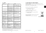
Страница 70: ...3 6 3 5 2 8 1 5 2 8 1 8 5 8 5 10 TECHNICAL DATA EN 11 FAULTS FAULT CAUSE REMEDIAL MEASURE Flow rate too low or no flow at all System separator not mounted in the flow direc tion Install the system sep...

Страница 71: ...ly binding signature ______________________________ This declaration certifies compliance with the named directives but does not contain any assurance of characteristics Dr D Ende Head of Research and...

Страница 72: ...142 143...
Страница 73: ...nfo perma trade de FR Aqua Partner 5 rue Br l e 67620 Soufflenheim T l 06 75 38 69 55 aqua partner outlook fr www aquapartner fr BE NL perma trade BeNeLux bvba Smiskensveld 32 1731 Relegem Asse Tel 00...

Отзывы: