124
125
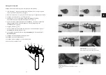
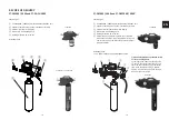
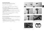
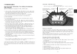
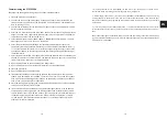
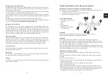
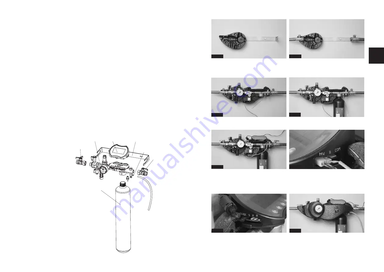
Fig. 1
Fig. 2
Fig. 3
Fig. 4
Installation of digital heating filling stations PT-FCS(D)5000
Observe the flow direction (arrow on filling station)
1. Fasten the holding bracket
⑤
to the wall with the screw set provided (fig.1) and push rear
insulating shell onto the retaining bracket
2. Mount pressure gauge and opposite blanking plug on system separator
⑥
3. Connect ball valves
②
to the installation (fig. 2)
4. Screw ball valves to digital heating filling station, attaching second rear insulation (fig. 3)
5. Screw in the PT-PS5000FD
permasoft
①
from underneath (fig. 4),
alternatively connect the PS-AD28000 adapter with the flexible connection hoses
for PT-PS28000E to the fitting.
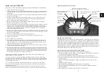
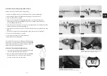
6. Push the electronics housing
③
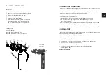
on (fig. 5)
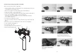
7. Plug in the conductance sensor (II) on the side of the electronics; possible on both sides
(fig.6, 7)
8.
If necessary, plug in the pulse cable (S) and/or signal cable to the relay (R) (fig.7)
9. Connect magnetic valve (MV) (fig. 6)
10. Connect power supply plug
11. Push the flushing hose
④
onto the bleed valve
12. Attach the front insulating shells
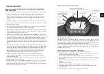
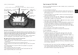
PT-FCS / PT-FCSD: Connections on the left:
24 V, pulse cable (S), conductance sensor (II),
signal cable (R)
PT-FCS / PT-FCSD: Connections on the right:
magnetic valve (MV), conductance sensor (II),
preparation for bidirectional communication (COM)
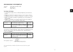
Fig. 5
Fig. 6
Fig. 7
Fig. 8
EN
①
②
②
③
④
⑤
⑥
Содержание PT-DA-CH5000
Страница 72: ...142 143...

