18
P/N 470880
Rev. K 5-31-06
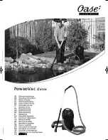
FROM POOL
TO POOL
FILTER
PUMP
CHECK
VALVE
CHECK
VALVE
VALVE
GATE
EXTERNAL BY-PASS VALVE
IF REQUIRED
GA
S
DR
AIN
SE
LE
CT
SP
A T
EM
P
HO
T
SE
RV
IC
E
PO
W
ER
SP
A
CO
LD
AU
X.
PR
ES
S
TS
TA
T
HE
AT
HO
T
PO
OL
TE
MP
CO
LD
PO
OL
TH
ER
MO
ST
AT
OF
F
Hig
h P
erfo
rma
nce
Co
mm
erc
ial
Ele
ctro
nic
Ign
itio
n H
eat
er
Mi
niM
ax
Se
rie
s
Installation (contd.)
WATER CONNECTIONS
VALVES
When any equipment is
located below the
surface of the pool or
spa, valves should be
placed in the circulation
piping system to isolate
the equipment from the
pool or spa.
Check valves are recommended to prevent back siphon.
CAUTION
Exercise care when installing chemical feeders
so as to not allow back siphoning of chemicals
into the heater, filters or pump.
WATER SUPPLY CONNECTIONS
The MiniMax pool and spa heaters require a constant flow of
filtered water with a positive pressure therefore it is mandatory
that the heater is always plumbed downstream from the pump
and filter.
The MiniMax Commercial series Pool and Spa heaters are
equipped with a 2 in. F.I.P. connections. When installing the
water connections, a minimum of three feet (3
’
) of copper
piping must be installed on the inlet and outlet of the heater.
Do not operate the heater unless water in pool or spa is at
proper level.
INSTALLATION & OPERATION OF
EXTERNAL BY-PASS VALVE
All commercial MiniMax pool heaters have an automatic
mechanical internal by-pass valve that allows the heater to
handle a maximum flow of 120 GPM. If the hydraulics of
the system is exceeding the 120 GPM, an external manual
by-pass
“ MUST”
be installed as shown in Figure 16, and a
thermometer
“MUST”
be installed in the threaded opening
located below the Pressure Relief valve on the header as
shown in Figure 15.
BELOW POOL INSTALLATION
If the heater is below water level, the pressure switch must
be adjusted. This adjustment must be done by a qualified
service technician. See the following CAUTION.
OUTLET
INLET
THERMOMETER
IN & OUT HEADER
IN
THE FOLLOWING PROCEDURE
WILL ASSIST YOU IN ADJUSTING
AND SETTING OF THE MANUAL
BY-PASS VALVE
1. Turn the heater off and close the external by-pass valve
completely.
2. Start the filtration system.
3. Allowing the system to run for at least 4 minutes,
record the temperature reading on the thermometer,
(this is the actual temperature of the pool or spa).
4. Turn the heater on and note the temperature, this is
your starting temperature.
5. Gradually open the manual by-pass valve until the
difference between the actual pool or spa temperature,
“this was your first temperature reading”, and
temperature shown on the thermometer with the heater
operating is equal to a 20 to 25 degree F. rise.
6. Once the manual by-pass is set to give you the proper
degree of rise, 20 to 25 degree’s, remove the handle from
the manual by-pass valve, this will avoid tempering.
Figure 15.
Figure 16.
Maximum
Minimum
Model
525
35
120
750
40
120
900
45
120
FLOW REQUIREMENTS
CAUTION
BELOW OR ABOVE POOL INSTALLATION
The water pressure switch is set in the factory at 1½
PSI. This setting is for a heater installed at pool level or
within 3’ above or 3’ below. If the heater is to be installed
more that 3’ above or 3’ below, the water pressure switch
must be adjusted by a qualified service technician.
FLOW SWITCH
If the heater is installed more the 6’ above the pool or
more than 10’ below the pool level, you will be beyond
the limits of the pressure switch and a flow switch must
be installed. Locate and install the flow switch externally
on the outlet piping from the heater, as close as possible
to the heater. Connect the flow switch wires in place of
the water pressure switch wires.