background image

f.

Table 4.5 provides the flow rate and pressure drop
information that corresponds to various system
temperature rise values (

D

T). The pressure drop

shown is for the boiler only. If there is significant
system pressure drop in the system, this should be
included when specifying circulators.

g. Table 4.6 provides a list of recommended

circulators for boilers on a secondary loop of a
primary/secondary system which uses water as a
heating medium.

h. Special consideration must be given if a glycol

based anti-freeze solution is used as a heating
medium. Propylene glycol has a higher viscosity
than water, therefore the system pressure drop will
be higher.

10.

Indirect Water Heater:

An indirect water heater should

be piped to a dedicated zone. The 

P

URE

F

IRE

boiler

provides electrical terminals for connecting a domestic
hot water (DHW) circulator. Examples of piping for
the indirect water heater are shown under subsection
“E”, System Piping of this section.

D. SYSTEM PIPING

1. Figure 4.4 shows a single boiler with multiple heating

zones. In this case, the DHW zone is piped in parallel
to the heating zones on the primary loop.

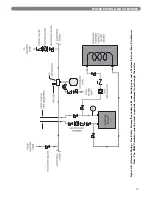
2. For a single boiler with one heating zone and one

DHW zone which utilizes an indirect water heater like
the Peerless Partner, pipe the boiler as shown in
Figure 4.5. In systems like this, the DHW circulator
must be sized to provide the minimum flow rate
through the boiler.

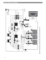
3. In Figure 4.6 an additional boiler is added and more

heating zones are shown. Notice that the two boilers
are piped in parallel on the secondary loop. This
maximizes the efficiency of the boilers since the lowest
temperature system water is returning to both boilers. 

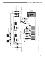
4. Figure 4.7 shows a multiple boiler system with several

different types of heat distribution units. This system
illustrates how different temperature zones can be
supplied from the same source by blending supply
and return water to the zone.

5. In Figure 4.8 zone valves are used instead of zone

circulators. Notice that the system is piped using
reverse return piping to help balance the flow through
the zones. If the zone lengths vary balancing valves
are required on each loop.

E. FREEZE PROTECTION

1. Glycol for hydronic applications is specially

formulated for heating systems. It includes inhibitors
which prevent the glycol from attacking metallic
system components. Make sure that the system fluid is
checked for correct glycol concentration and inhibitor
level.

2. Use only inhibited polypropylene glycol solutions of

up to 50% by volume. Ethylene glycol is toxic and
can chemically attack gaskets and seals used in
hydronic system.

3. The anti-freeze solution should be tested at least once

per year and as recommended by the manufacturer of
the product.

4. Anti-freeze solutions expand more than water. For

example, a 50% by volume solution expands 4.8%
with a 148°F temperature rise while water expands
about 3% for the same temperature increase.
Allowance for this expansion must be considered in
sizing expansion tanks and related components.

5. The flow rate in systems utilizing glycol solutions

should be higher than in a water system to
compensate for decreased heating capacity of the fluid.

13

WATER PIPING AND CONTROLS

Table 4.5: Boiler Pressure Drop and Flow Rates for

Various System Temperature Rise Values

D

T

(°F)

Flow Rate & Pressure Drop

PF-50

PF-80

PF-110

PF-140

GPM

FT

GPM

FT

GPM

FT

GPM

FT

40

n/a

3.20

3.2

4.40

3.1

5.65

2.3

35

2.28

2.3

3.65

4.0

5.02

3.8

6.45

2.9

30

2.66

2.9

4.26

5.1

5.86

5.0

7.53

3.7

25

3.20

3.7

5.12

7.0

7.03

6.8

9.03

5.2

20

4.00

5.4

6.39

10.4

8.79

10.0 11.29

8.0

15

5.33

8.8

8.53

17.5 11.72 17.0 15.05 14.0

10

7.99

18.5

n/a

n/a

n/a

The circulator sizing given is for primary/secondary
installations only. The system circulators must be
sized based on the flow and pressure drop
requirements of the system.

NOTICE

Table 4.6: Circulator Selection Chart

Circulator selections are based on boiler net output which
includes a 1.15 pick-up factor for piping losses.

Pump

Manufacturer

Temp

Difference

PF-50

PF-80

PF-110

PF-140

Taco

10

0014

N/A

N/A

N/A

Grundfos

UPS 26-99

N/A

N/A

N/A

Taco

15

007

0014

0014

0014

Grundfos

UPS 15-58 UPS 26-99 UPS 26-99 UPS 26-99

Taco

20

006

008

008

007

Grundfos

UPS 15-58 UPS 15-58 UPS 26-99 UPS 26-99

Taco

25

003

007

007

007

Grundfos

UPS 15-58 UPS 15-58 UPS 15-58 UPS 15-58

Taco

30

003

006

007

007

Grundfos

UPS 15-58 UPS 15-58 UPS 15-58 UPS 15-58

Taco

35

003

006

006

006

Grundfos

UPS 15-58 UPS 15-58 UPS 15-58 UPS 15-58

Taco

40

N/A

003

006

006

Grundfos

N/A

UPS 15-58 UPS 15-58 UPS 15-58

Содержание PF-110

Страница 1: ...PUREFIRE Boilers Gas Installation Operation Maintenance Manual As an ENERGY STAR Partner PB Heat LLC has determined that this product meets the ENERGY STAR guidelines for energy efficiency ...

Страница 2: ...N PIPING 24 A GENERAL 24 B CONDENSATE SYSTEM 24 C CONDENSATE DRAIN PIPE MATERIAL 24 D CONDENSATE DRAIN PIPE SIZING 24 E CONDENSATE DRAIN PIPE INSTALLATION 25 7 ELECTRICAL CONNECTIONS 26 A GENERAL 26 B CUSTOMER CONNECTIONS 26 C INTERNAL WIRING 26 8 BOILER CONTROL INTERNAL WIRING OPERATION 29 A CONTROL OVERVIEW 29 B IGNITION SEQUENCE 31 C BOILER CONTROL 33 D CENTRAL HEATING 36 E DOMESTIC HOT WATER D...

Страница 3: ...ions and make special notice of potential hazards The definition of each of these categories in the judgement of PB Heat LLC are as follows USING THIS MANUAL Indicates special attention is needed but not directly related to potential personal injury or property damage NOTICE Indicates a condition or hazard which will or can cause minor personal injury or property damage CAUTION DANGER Indicates a ...

Страница 4: ...el where the gas equipment is to be installed AND on each additional level of the dwelling building or structure served by the side wall horizontal vented gas fueled equipment In the event that the side wall horizontally vented gas fueled equipment is installed in a crawl space or an attic the hard wired carbon monoxide detector with alarm and battery back up may be installed on the next adjacent ...

Страница 5: ...on 3 of this manual Venting for specific instructions for piping combustion air E PLANNING THE LAYOUT 1 Prepare sketches and notes showing the layout of the boiler installation to minimize the possibility of interferences with new or existing equipment piping venting and wiring 2 The following sections of this manual should be reviewed for consideration of limitations with respect to a Venting and...

Страница 6: ...nting bracket has 4 holes on 16 centers This is intended to give the installer the ability to mount the bracket on two wall studs spaced at this interval If existing wall studs are spaced differently or if the desired location is not in line with the wall studs additional support is required 5 If the boiler is wall mounted be sure that the wall provides adequate support for the boiler 6 Be sure to...

Страница 7: ...f the vent pipe and air inlet pipe terminations penetrate the wall at the same level the minimum distance between them is 8 center to center e For multiple boiler installations the minimum distance between the inlet of one boiler to the exhaust of another is 8 center to center f See Figure 3 1 for an illustration of vent spacing for multiple boilers VENTING AIR INLET PIPING 3 VENTING AIR INLET PIP...

Страница 8: ...al be above or below the aforementioned equipment unless the 4 foot horizontal distance is maintained Do not locate the exhaust exit terminal over public walkways where condensate could drip and create a hazard or nuisance When adjacent to public walkways locate the exit terminal at least 7 feet above grade Do not locate the exit termination directly under roof overhangs to prevent icicles from fo...

Страница 9: ...st and Air Inlet Pipe Penetration at Different Elevations Figure 3 4 Exhaust and Air Inlet Pipe Penetration at the Same Elevation Figure 3 5 Optional Stainless Steel Vent Kit Installation Figure 3 6 Optional Concentric PVC Vent Kit Installation ...

Страница 10: ...ional MUGROTM vent adapter 54155 Contact your PB Heat LLC representative for more information on this option 3 The total combined length of exhaust vent and air intake piping is 200 equivalent feet 60 m a The equivalent length of elbows tees and other fittings are listed in Table 3 2 b The equivalent length can be calculated as follows This is well below the 200 feet maximum equivalent length If t...

Страница 11: ...on vent system the following steps must be carried out for each appliance that remains connected These steps are to be completed for each appliance while the other appliances that remain connected are not in operation a Seal any unused openings in the common venting system b Visually inspect the venting system for proper size and horizontal pitch Verify that there is no blockage or restriction lea...

Страница 12: ...installed must have an air elimination device As the system water is heated dissolved oxygen and carbon dioxide will separate from the liquid An air elimination device such as a TACO 430 Series Air Scoop with automatic air vent is required to remove the dissolved gasses from the system preventing corrosion in the piping system and eliminating system noise 3 Expansion Tank An expansion tank such as...

Страница 13: ...ot be used on glycol systems unless close supervision of the glycol solution is practiced 7 Back Flow Preventer A back flow preventer check valve is required by some jurisdictions to prevent water in the hydronic system from backing up into the city water supply This is especially important on systems in which glycol solution is used as the heating medium 8 Pressure Relief Valve The boiler pressur...

Страница 14: ...0 x 500 d Table 4 4 shows the pressure drop in feet of water for a flow rate for each boiler model that produces a temperature difference of 20 F e The boiler pressure drop for various flow rates can be determined using Figure 4 3 the PUREFIRE Boiler Circulator Sizing Graph 12 WATER PIPING AND CONTROLS PUREFIRE Model Boiler Input Btu hr kW Net I B R Output Btu hr kW PF 50 50 000 14 7 40 000 11 7 P...

Страница 15: ...OTECTION 1 Glycol for hydronic applications is specially formulated for heating systems It includes inhibitors which prevent the glycol from attacking metallic system components Make sure that the system fluid is checked for correct glycol concentration and inhibitor level 2 Use only inhibited polypropylene glycol solutions of up to 50 by volume Ethylene glycol is toxic and can chemically attack g...

Страница 16: ...14 WATER PIPING AND CONTROLS Figure 4 4 Recommended Piping One Boiler Primary Secondary with Two Zones Zone Circulator ...

Страница 17: ...NG AND CONTROLS Figure 4 5 Alternate Piping One Boiler Primary Secondary with one heating zone and a Peerless Partner Zone Circulators Note The DHW Circulator must be sized to provide minimum flow through the boiler ...

Страница 18: ...16 WATER PIPING AND CONTROLS Figure 4 6 Two Boilers Primary Secondary with Four Zones Zone Circulator ...

Страница 19: ...17 WATER PIPING AND CONTROLS Figure 4 7 Three Boilers Primary Secondary with Five Zones Zone Circulator ...

Страница 20: ...18 WATER PIPING AND CONTROLS Figure 4 8 Three Boilers Primary Secondary with Four Zones Zone Valves ...

Страница 21: ...0 ppm of calcium b Less than 50 ppm of magnesium c Less than 100 ppm 5 grains gallon of total hardness d Less than 25 ppm of chloride e Less than 25 ppm of sulfate 12 Check with the local water supplier for chemical properties of the water 13 The following test will determine if the water is of the appropriate hardness Collect a sample of 50 water to 50 propylene glycol Let the solution stand for ...

Страница 22: ...20 WATER PIPING AND CONTROLS PEERLESS PUREFIRE BOILER PEERLESS PUREFIRE Figure 4 9 Boiler in conjunction with a Chilled Water System Figure 4 10 Boiler Connected to a Heating Coil in a Forced Air System ...

Страница 23: ...ll a ground joint union between the sediment trap and the boiler to allow service to the appliance 4 Install a service valve as shown in Figure 5 1 to allow the gas supply to be interrupted for service 5 Maintain a minimum distance of 10 feet between the gas pressure regulator and the boiler 21 FUEL PIPING 5 FUEL PIPING Use a pipe joint sealing compound that is resistant to liquefied petroleum gas...

Страница 24: ...firing g Turn off the boiler and close the gas shutoff valve h Remove the manometer tube from the pressure tap fitting i Turn the internal screw to close the valve j Turn on the gas shutoff valve and boiler service switch k Fire the boiler and check for fuel gas odor around the gas valve If an odor is evident check to make sure that the pressure tap fitting is closed 4 All gas piping must be leak ...

Страница 25: ...ncrease the gas flow rate increasing CO2 Markings adjacent to the throttle screw show and indicating this operation c The recommended CO2 settings are given in Table 5 4 In no case should the boiler be allowed to operate with CO emissions above 150 ppm 2 Refer to Section 3 Venting and Air Intake for information on obtaining vent samples from this boiler 23 FUEL PIPING Figure 5 2 Gas Valve Venturi ...

Страница 26: ...e boiler from operating if the condensate line is clogged 3 Condensate Float Switch This switch will prevent the boiler from operating if the condensate outlet is clogged before the level of condensate reaches the heat exchanger 4 Condensate Neutralizer Container The condensate neutralizer container is an additional transparent container near the front of the boiler Fill this container with the co...

Страница 27: ...s away from the boiler with a pitch of 1 4 per foot of pipe 3 If the boiler condensate drain is above the level of a gravity drain a condensate pump should be used Table 6 1 lists several available brands Contact your PB Heat LLC Distributor for availability 25 CONDENSATE DRAIN PIPING Brand Name Model Number Little Giant VCMA 15UL Beckett CB151LSUL Hartell KT 15 1UL Table 6 1 Recommended Condensat...

Страница 28: ...d even when the service switch is off C INTERNAL WIRING Figure 7 4 on the following page shows the complete boiler wiring schematic The following is a list of internal wiring components 1 User Interface The user interface is attached to the front of the electrical junction box and is accessible by removing the tinted lens on the front of the boiler This interface allows users and installers to com...

Страница 29: ...control also senses flame through the ignition electrode 9 Gas Valve The gas valve is connected through a special cord and connector The connector is attached to the valve with a screw 10 Ignition Electrode This electrode is located on the left side of the heat exchanger front plate A 10 000 volt charge is initiated by the control to provide a spark for lighting the burner After the burner lights ...

Страница 30: ...28 ELECTRICAL CONNECTIONS Figure 7 4 Internal Wiring Schematic ...

Страница 31: ...rmostat and Outdoor Reset Call for Heat signal from thermostat with boiler supply target temperature calculated using outdoor temperature 8 D 1 36 2 Full Outdoor Reset Continuous heat demand with boiler supply target temperature calculated using outdoor temperature 8 D 1 36 3 Permanent Demand Continuous heat demand with user selected boiler supply target temperature 8 D 1 36 4 0 10 V Input to modu...

Страница 32: ...ow water cutoff in jurisdictions where it is required 8 C 4 35 Vent Temperature Safety Limit Reduces the firing rate if the vent temperature approaches the maximum limit of the vent material If the vent temperature continues to climb the PUREFIRE control will shut down the boiler 8 C 2 35 Outdoor Reset The PUREFIRE control changes the boiler supply target temperature to compensate for changes in l...

Страница 33: ...milliseconds 5 seconds 10 seconds maximum Table 8 5 Ignition Sequence Period Demand Status User Interface Display Standby No demand is present If the power is on to the PUREFIRE boiler and there is no heat demand the user interface will display Standby and show the boiler supply temperature in the lower right corner The time in 24 hour format is shown in the upper right When a heat demand either C...

Страница 34: ...ignition cycle again If there are three consecutive ignition failures the control will post purge and lockout Burner On A heat demand must be present for the control to stay in this period Once the flame signal is established the burner will run until the demand is satisfied the setpoint is exceeded or a blocking error occurs The maximum run period for the burner is 24 hours If the boiler runs con...

Страница 35: ...ase circulation through the boiler is to be provided by the CH pump when in a central heating mode When satisfying a DHW demand the circulation through the boiler is provided by the DHW pump Figure 8 2 8 3 both show the electrical connections from the boiler to the circulators Either the CH pump or the DHW pump can be energized but they can never run simultaneously BOILER CONTROL INTERNAL WIRING O...

Страница 36: ...typical piping for Pump Mode 2 for central heating only and Figure 8 7 shows typical piping for central heating with a DHW tank This mode is preferred if multiple heating zones are used The general pump operates to assure proper flow through the boiler at all times Like mode 1 the general pump always runs when the boiler is operating The Ch pump provides circulation to CH zones and the DHW pump pr...

Страница 37: ...ignition sequence described in section 8 B The control will operate the burner at minimum power until the both the supply and return boiler temperature are more than 9 F 5 C above the freeze protection setpoint While this function is active the interface panel will display the following 4 Additional Safety Functions The PUREFIRE boiler control is equipped with terminals for either a low water cuto...

Страница 38: ...hen the boiler supply temperature approaches the target setpoint the burner will modulate down to decrease the input If the temperature begins to decrease the control will increase the input rate 3 Outdoor Reset Operation To maximize fuel savings PUREFIRE boilers are factory equipped for outdoor reset operation The following describes the operating principal of this feature Operating Principle Hea...

Страница 39: ... condition It will also help if too low of a value is chosen for the boiler design and or mild weather temperature This value will continue to increase by the Temp value if the demand continues through consecutive Time periods The value is allowed to exceed the design temperature but can never exceed the boiler maximum temperature Warm Weather Shutdown In any CH mode utilizing outdoor reset the wa...

Страница 40: ... C DANGER Water temperatures over 125 F can instantly cause severe burns or death from scalding Children elderly and disabled individuals are at the highest risk of scalding See instruction manual for the indirect tank before setting the water heater temperature Instruct users to feel the water temperature before bathing or showering Anti scald valves are recommended Be sure to use only the tank s...

Страница 41: ... call for heat ends the pumps will operate to dump heat to the indirect tank Which pumps operate depends on the pump mode and DHW mode selected Pump Mode 0 DHW Mode 1 2 The DHW pump will operate to divert excess boiler heat to the indirect tank The CH pump shuts down until this is accomplished Pump Mode 1 DHW Mode 1 2 The General pump will operate and the 3 way valve will direct excess boiler heat...

Страница 42: ...e boiler Flame Signal Failures Pressing the M key again will display the Flame Signal Failures Screen The flame signal is an indication of combustion stability of the burner If this value is below 1 7 µA microampere the control will close the gas valve and the burner will recycle through the ignition cycle The flame signal should be above 5 0 µA in normal operation If the control loses its flame s...

Страница 43: ... and all manual gas valves to the boiler Check to see if the LCD display is lit The control will display Standby 3 Refer to Section 8 Boiler Control to set up the control for the desired operation 4 Use the ignition sequence Figure 8 1 to follow the light off and shutdown sequences and to assist in troubleshooting operation problems If the boiler does not function properly consult Section 10 Troub...

Страница 44: ...n either of these instances falls outside the parameters listed in Table 4 5 turn off the boiler and contact your PB Heat representative f Be sure to set the System Test mode to Off so that the boiler will modulate correctly in accordance with the load g After removing the analysis probe from the vent pipe insert a PVC or Stainless Steel pipe plug into the test port See Figure 9 3 h Record the com...

Страница 45: ...ner Do not try to light the burner by hand B BEFORE OPERATING smell all around the appliance area for gas Be sure to smell next to the floor because some gas is heavier than air and will settle on the floor WHAT TO DO IF YOU DO SMELL GAS Do not try to light any appliance Do not touch any electric switch do not use any phone in your building Immediately call your gas supplier from a neighbor s phon...

Страница 46: ...e the problem and increase the likelihood of boiler damage Instead shut off the gas supply to the boiler at the gas service valve CAUTION DANGER When servicing or replacing components that are in direct contact with the boiler water be certain that There is no pressure in the boiler Pull the release on the relief valve Do not depend on the pressure gauge reading The boiler water is not hot The ele...

Страница 47: ...arth connected or internal hardware error Check boiler ground and harness E23 NET FREQUENCY ERROR 45 Mains frequency differs more than 2 from 60Hz Contact PB Heat Representative E24 POOR GROUND 46 Earth connection is not ok Check boiler ground and harness E26 BLOCKED CONDENSATE DRAIN 41 Condensate drain blocked Check condensate tanks hoses condensate switch and harness E30 HIGH STACK TEMPERATURE 3...

Страница 48: ...ading on the supply thermistor Replace it if necessary A04 INTERNAL ERROR GAS VALVE RELAY 5 Gas Valve Relay Problems Replace control A05 INTERNAL ERROR SAFETY RELAY 6 Safety Relay Problems Replace Control A09 INTERNAL SOFTWARE ERR RAM ERROR 9 Internal Software Error Replace Control A09 INTERNAL SOFTWARE ERR 27 Internal Software Error Replace Control A09 INTERNAL SOFTWARE ERR 28 Internal Software E...

Страница 49: ...eck igniter to be sure there is not short to ground A23 FLOW_SW_NOT_OPEN 25 CH flow switch not working 1 Check for electrical continuity between wires connected to terminals 9 10 from field supplied flow switch 2 If there is continuity when the circulator is off there is a system piping or circulator control problem A24 FLOW_SW_NOT_CLOSED 26 CH flow switch not working 1 Check for electrical contin...

Страница 50: ...to clear the valve seat of foreign matter It may take some time to determine if the valve has shut completely e If the valve continues to leak it must be replaced before the boiler is returned to operation f Check that operating pressure and temperature have returned to normal g Check again to confirm that valve has closed completely and is not leaking 3 Test low water cut off if used as described...

Страница 51: ...de so the flow can be observed c Remove four screws on the 1 2 NPT connector at the gas valve intake and disconnect the gas valve electrical connector d Remove the six 10 mm nuts from the burner plate assembly Disconnect wire leads to the spark igniter and flame sensor Disconnect two Molex plugs from blower motor e Pull the entire burner plate towards you to access the heat exchanger coils 2 Using...

Страница 52: ...y result in a flame lockout This is normal and will require you to recycle the unit until this clears up This is caused by water still present in the combustion chamber 6 Inspect exhaust vent and air intake vents for proper support and joint integrity Repair as necessary Refer to Section 5 VENTING 7 Inspect exhaust vent and air intake vent terminations for obstructions 50 MAINTENANCE Leaks in the ...

Страница 53: ... PF 50 50 MBH 1410 2802 3360 PF 80 80 MBH 1890 3247 4800 PF 110 110 MBH 1980 3247 5280 PF 140 140 MBH 1770 3247 4800 SERIES PEERLESS PUREFIRE BOILER RATINGS DIMENSIONS Boiler Model Input MBH Heating Capacity MBH Net I B R Ratings MBH AFUE Dimensions inches Min Max A B PF 50 16 50 46 40 95 0 13 1 2 3 3 4 PF 80 26 80 73 63 95 2 13 1 2 4 7 8 PF 110 36 110 101 88 95 8 19 7 5 8 PF 140 46 140 130 113 95...

Страница 54: ...PARTS Repair parts are available from your installer or by contacting PB Heat LLC 131 S Church St Bally PA 19503 Note Remember to include boiler model number and serial number when ordering parts 13 REPAIR PARTS ...

Страница 55: ...ok Bolt 2 5451 21 Convenience Outlet 1 54136 22 Hex Nut 8 32 with Lockwasher 4 51573 23 Control Module 852MN PF 50 1 54162 Control Module 852MN PF 80 1 54163 Control Module 852MN PF 110 1 54164 Control Module 852MN PF 140 1 54165 24 Switch Round Toggle 120 VAC 1 6049 25 Vent Air Inlet Adapter 1 54135 26 Gasket Vent Adapter 1 54133 27 Screw 10 x 5 8 LG Phil Pan HD Type A Zinc 6 5507 Wiring Harness ...

Страница 56: ...54 REPAIR PARTS ...

Страница 57: ...ew M4 X 8 mm Stainless 1 49 Washer Stainless 1 50 Insulation Target Wall 1 54185 51 Heat Exchanger PF 50 1 5410 Heat Exchanger PF 80 1 5411 Heat Exchanger PF 110 1 5412 Heat Exchanger PF 140 1 5413 52 Gasket Blower to Channel 1 54122 53 Blower PF 50 PF 80 1 54189 Blower PF 110 1 54190 Blower PF 140 1 54191 54 Screw M5 x 12mm 4 55 Blower Adapter Plate 1 56 Screw M4 x 10mm 3 57 Swirl Plate PF 50 Blu...

Страница 58: ...56 REPAIR PARTS ...

Страница 59: ... 3 Clamp 3 4 ID Tubing 4 54138 4 Pre formed 3 4 ID Tubing Tank to Jacket with 2 clamps 1 54172 5 Tubing 3 4 ID x 1 8 Wall PVC 19 5 LG 19 5 5417 6 Tank Condensate Collector 1 54120 7 Condensate Switch Float Assembly with Cap 1 54137 8 Tubing 3 4 ID x 1 8 Wall PVC 6 5 LG 6 5 5417 9 Clamp 5 8 ID Tubing 2 54139 10 Tubing 5 8 ID x 1 8 Wall PVC 9 5 5416 ...

Страница 60: ...58 APPENDIX A STATUS SCREENS APPENDIX A STATUS SCREENS ...

Страница 61: ...59 APPENDIX A STATUS SCREENS ...

Страница 62: ...60 APPENDIX A STATUS SCREENS ...

Страница 63: ...61 APPENDIX B USER MENU APPENDIX B USER MENU ...

Страница 64: ...62 APPENDIX C INSTALLER MENU APPENDIX C INSTALLER MENU ...

Страница 65: ...63 APPENDIX C INSTALLER MENU ...

Страница 66: ...64 APPENDIX C INSTALLER MENU ...

Страница 67: ...re Drop at Startup High Fire Outlet Gas Pressure in w c Low Fire Outlet Gas Pressure in w c Combustion Readings Flame Signal High Fire µA Flame Signal Low Fire µA CO High Fire CO Low Fire CO High Fire ppm CO Low Fire ppm Fan Speed High Fire Fan Speed Low Fire Excess Air High Fire Excess Air Low Fire Exhaust Temperature High Fire F Exhaust Temperature Low Fire F System Information Water Pressure Co...

Страница 68: ...66 NOTES ...

Страница 69: ...67 NOTES ...

Страница 70: ...his manual is the property of the owner and must be affixed near the boiler for future reference TO THE OWNER This boiler should be inspected annually by a Qualified Service Agency PF8022 R1 10 08 2M Printed in U S A 2008 PB HEAT LLC 131 S CHURCH STREET BALLY PA 19503 CONTROLS ASME ...

Отзывы: