A. GENERAL
1. Size water supply and return piping in accordance
with system requirements. Do not use smaller
diameter piping than the boiler connections.
2. If the
P
URE
F
IRE
boiler is used to replace an existing
boiler, make sure that the system piping is thoroughly
cleaned and free from debris before installing this boiler.
3. In hydronic systems where sediment may exist, install
a strainer in the boiler return piping to prevent large
particles and pipe scale from entering the boiler heat
exchanger. Use a large mesh screen in the strainer.
4. Install this boiler so that the gas ignition system
components are protected from water (dripping,
spraying, etc.) during operation and service (circulator
replacement, condensate trap cleaning, sensor
replacement, etc.).
B. OPERATING PARAMETERS
1. The
P
URE
F
IRE
boiler is designed to operate in a closed
loop hydronic system under forced circulation. This
requires the system to be completely filled with water
and requires a minimum water flow through the boiler
to operate effectively.
2. The minimum system pressure is 14.5 PSI (69 kPa)
3. Table 4.1 lists the minimum flow rates for each
P
URE
F
IRE
model. If a glycol solution is to be used,
contact your PB Heat, LLC representative for
minimum flow rates.
Section 4.E provides detailed information about using
glycol for freeze protection.
Table 4.2 provides the water volume of the heat
exchanger including the supply and return pipes that
are attached at the factory.
C. SYSTEM COMPONENTS
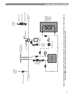
Figure 4.1 shows the symbol key for piping diagrams in
this section. The following are brief descriptions of system
components.
1.
Pressure/Temperature Gauge:
A combination
pressure/temperature gauge is provided with each
P
URE
F
IRE
boiler to be mounted in the piping from the
boiler supply to the system as shown in Figure 4.2.
Most local codes require this gauge.
2.
Air Elimination:
Any closed loop hydronic system in
which the
P
URE
F
IRE
boiler is installed must have an air
elimination device. As the system water is heated,
dissolved oxygen and carbon dioxide will separate
from the liquid.
An air elimination device (such as a TACO 430 Series
Air Scoop with automatic air vent) is required to
remove the dissolved gasses from the system
preventing corrosion in the piping system and
eliminating system noise.
3.
Expansion Tank:
An expansion tank (such as a Bell &
Gossett Series HFT) is required to provide room for
expansion of the heating medium (water or glycol
solution). Consult the expansion tank manufacturer's
instructions for specific information regarding
installation. The expansion tank is to be sized for the
required system volume and capacity. In addition, be
sure that the expansion tank is sized based on the
proper heating medium. Glycol solutions may expand
more than water for a similar temperature rise.
4.
Y-Type Strainer:
In older systems where a significant
amount of sediment may be present, it may be
necessary to install a Y-type strainer. The strainer
should be checked often and cleaned during the first
few months of operation to assure that sediment does
not reach the heat exchanger and clog the passages.
Use a large mesh screen in the strainer.
10
WATER PIPING AND CONTROLS
4. WATER PIPING & CONTROLS
Use only inhibited propylene glycol solutions which
are specifically formulated for hydronic systems.
Unlike automotive antifreeze, solutions for hydronic
applications contain corrosion inhibitors that will
protect system components from premature failure
due to corrosion.
CAUTION
Use only inhibited propylene glycol solutions which
are specifically formulated for hydronic systems.
Ethylene glycol is toxic and may cause any
environmental hazard if a leak or spill occurs.
WARNING
P
URE
F
IRE
Model
Minimum Flow Rate
Water
GPM (LPM)
50% Glycol
Solution
GPM (LPM)
PF-50
2.2 (8.3)
2.8 (10.6)
PF-80
3.3 (12.5)
4.1 (15.5)
PF-110
4.4 (16.7)
5.5 (20.8)
PF-140
5.5 (20.8)
6.8 (25.7)
Table 4.1: Minimum Flow Rate
P
URE
F
IRE
Model
Total Water Capacity
Gallons (Liters)
PF-50
0.62 (2.35)
PF-80
0.72 (2.73)
PF-110
0.89 (3.37)
PF-140
1.25 (4.73)
Table 4.2: Heat Exchanger Water Capacity
Содержание PF-110
Страница 18: ...16 WATER PIPING AND CONTROLS Figure 4 6 Two Boilers Primary Secondary with Four Zones Zone Circulator ...
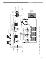
Страница 19: ...17 WATER PIPING AND CONTROLS Figure 4 7 Three Boilers Primary Secondary with Five Zones Zone Circulator ...
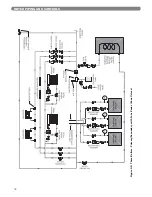
Страница 20: ...18 WATER PIPING AND CONTROLS Figure 4 8 Three Boilers Primary Secondary with Four Zones Zone Valves ...
Страница 30: ...28 ELECTRICAL CONNECTIONS Figure 7 4 Internal Wiring Schematic ...
Страница 56: ...54 REPAIR PARTS ...
Страница 58: ...56 REPAIR PARTS ...
Страница 60: ...58 APPENDIX A STATUS SCREENS APPENDIX A STATUS SCREENS ...
Страница 61: ...59 APPENDIX A STATUS SCREENS ...
Страница 62: ...60 APPENDIX A STATUS SCREENS ...
Страница 63: ...61 APPENDIX B USER MENU APPENDIX B USER MENU ...
Страница 64: ...62 APPENDIX C INSTALLER MENU APPENDIX C INSTALLER MENU ...
Страница 65: ...63 APPENDIX C INSTALLER MENU ...
Страница 66: ...64 APPENDIX C INSTALLER MENU ...
Страница 68: ...66 NOTES ...
Страница 69: ...67 NOTES ...


