45
Swapping the heat exchanger type
The FOCUS unit can be equipped and operated with two different types of heat exchanger:
•
Cross-counterflow heat exchanger made from plastic (standard heat exchanger)
•
Cross-counterflow enthalpy exchanger (membrane moisture heat exchanger)
1. Perform work steps 1 to 6 as described in 5.7.1.
2. Insert the relevant heat exchanger type while following the instructions for Fig. 42 and then perform work steps
9 to 10 as described in 5.7.1.
3. Parametrise the frost protection mode according to 4.3.2.3 in the menu Settings / sub-menu Frost protection
for the concerned heat exchanger type.
For a standard heat exchanger only the frost protection modes eco or safe may be set!
Swapping the heat exchanger for the summer box
The summer box is not capable of transferring heat or moisture. Instead, this module can be used to
replace the heat exchanger for summer ventilation while maintaining a supply air and extract air
mode!
In doing so, proceed as follows:
1. Perform work steps 1 to 6 as described in 5.7.1.
2. Insert the summer box module and perform work steps 9 to 10 as described in 5.7.1.
Error display and troubleshooting
The unit control system is equipped with an internal system for recognizing faults. The error messages display and
the error forecast are in line with the presentation possibilities of the connected control panel.
As a reaction to an error status, the fans are shut down.
Error display with LED control panel
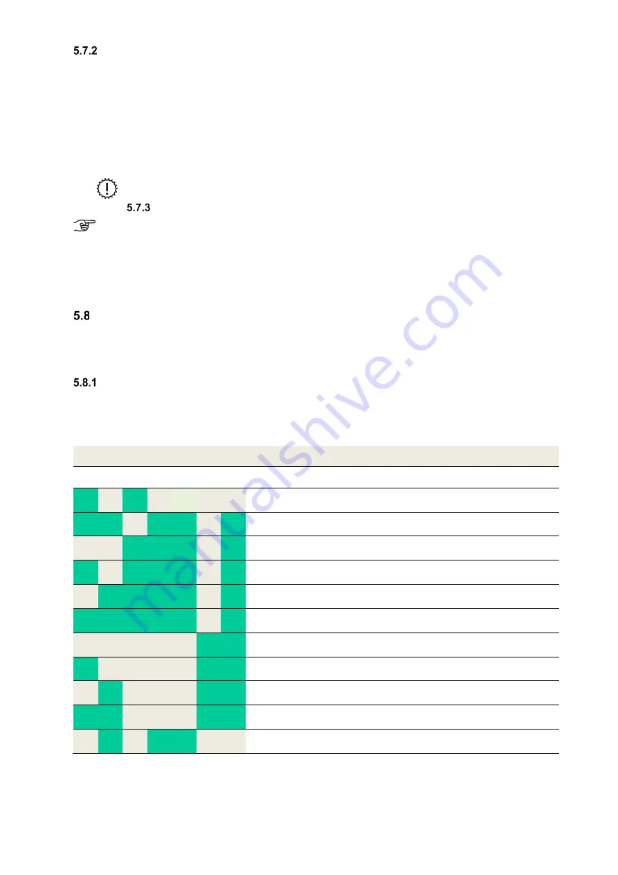
The display of errors with the LED control panel is according to point 4.2.1.2. In addition to indicating the error states,
an LED code is generated via LED L1...L7, which displays the significance of the error in a binary fashion.
Suggestions for the checks / measures for the potential elimination of the error status are given in Table 39.
The following LED combinations for displaying the error codes marked with “x” apply:
LED combination
Error Message
Possible cause
L1 L2 L3 L4 L5 L6 L7
x
x
Supply air temperature is too low
minimal supply air temperature <
nominal value
x
x
x
x
x
BUS version incompatible
Software versions of the
components not compatible
x
x
x
x
Too many units connected
Too many components connected
to the BUS
x
x
x
x
x
Fan slave not connected
Missing BUS communication
x
x
x
x
x
Fan slave communication error
Missing BUS communication
x
x
x
x
x
x
Defroster communication error
Missing BUS communication
x
x
Heating register communication
error
Missing BUS communication
x
x
x
Communication error ground heat
exchanger shutter
Missing BUS communication
x
x
x
General communication error
Missing BUS communication
x
x
x
x
Heater does not go off
BUS thermostat error
x
x
x
General GHE error
Missing BUS communication with
the control panel (GHE)
Table 38: Overview binary error encoding with LED control panel
Содержание FOCUS 200 Base
Страница 1: ...Translation of the original instruction manual Heat Recovery Unit FOCUS F 200...
Страница 49: ...49 Dimensions Fig 43 Dimensional drawing FOCUS...
Страница 50: ...50 FOCUS circuit plan Fig 44 Terminal assignment circuit diagram FOCUS...
Страница 51: ...51 Master Controller terminal assignment Fig 45 Master Controller terminal assignment...


