38
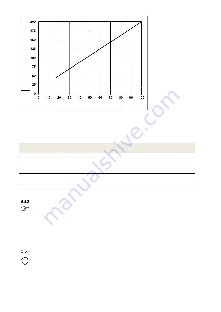
Fig. 36: Diagram 1, values to be set for the nominal air volume flow FOCUS unit with fan speed 2 (FS2)
5.5.2.2 Adjusting the nominal air volume flow with LED control panel
To adjust the ventilation system, the speed corresponding to the nominal air volume flow is set on the LED control
panel. The 7 speeds of the LED control panel are allocated nominal values for the fans at the factory according to
Table 29. The speed to be set for the nominal air volume flow must correspond to the nearest nominal value from
diagram 1 Fig. 36.
LED control panel
speed
Preselected nominal value [%]
1
17
2
25
3
40
4
53
5
68
6
83
7
100
Table 29Values to be set for the nominal air volume flow FOCUS with Led control panel
Adjusting the valves
At the start of volume flow measurement, make sure that the supply air and extract air valves
are open as wide as possible.
•
Set the fans to the nominal air volume flow
•
Adjust the valve orifices, throttle valves or throttle foam inserts
•
Measure the volume flows at the outlets using a volume flow hood and flow meter (see air volume protocol)
•
Readjust the valves
•
Lock the valves, shutters and throttles in their adjusted positions
•
Record the set air volumes and all other settings in the documentation intended for this purpose
Menu settings by qualified persons/service staff
Changes to the password-protected parameters may only be carried out by qualified persons
or service staff!
Preselected nominal value [%]
Sy
st
em a
ir v
ol
ume
fl
ow
[m
3
/h]
Содержание FOCUS 200 Base
Страница 1: ...Translation of the original instruction manual Heat Recovery Unit FOCUS F 200...
Страница 49: ...49 Dimensions Fig 43 Dimensional drawing FOCUS...
Страница 50: ...50 FOCUS circuit plan Fig 44 Terminal assignment circuit diagram FOCUS...
Страница 51: ...51 Master Controller terminal assignment Fig 45 Master Controller terminal assignment...


