32
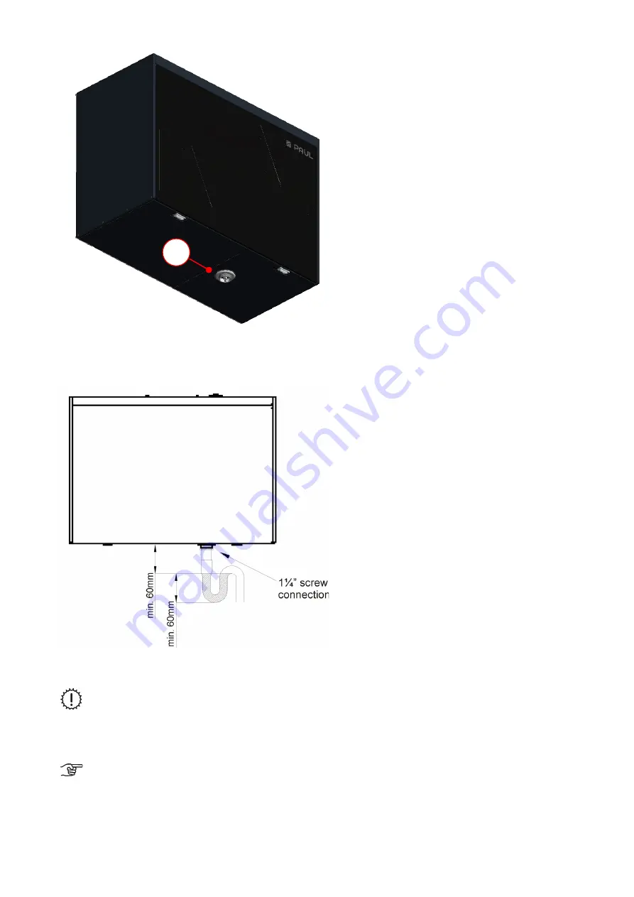
Fig. 28: Sink valve screw connection on unit version LEFT
A siphon must be attached to the screw connection so that the upper edge of the surge tank is at least 60 mm below
the screw connection and the minimum liquid level is 60 mm.
Fig. 29: Condensate drain (version LEFT)
The siphon must not be connected directly to the sewer tunnel network (e.g. whereby the
condensate flows freely into a funnel with a siphon connected to the sewer tunnel)
Siphons can dry out! The siphon must always be topped up with water when:
•
The unit is commissioned
•
The siphon starts making (slurping/gurgling) noises
A dry siphon is generally recommended, especially when using an enthalpy exchanger!
(No
functional restrictions if it dries out, no need for a 2nd siphon)
A
Содержание FOCUS 200 Base
Страница 1: ...Translation of the original instruction manual Heat Recovery Unit FOCUS F 200...
Страница 49: ...49 Dimensions Fig 43 Dimensional drawing FOCUS...
Страница 50: ...50 FOCUS circuit plan Fig 44 Terminal assignment circuit diagram FOCUS...
Страница 51: ...51 Master Controller terminal assignment Fig 45 Master Controller terminal assignment...


