24
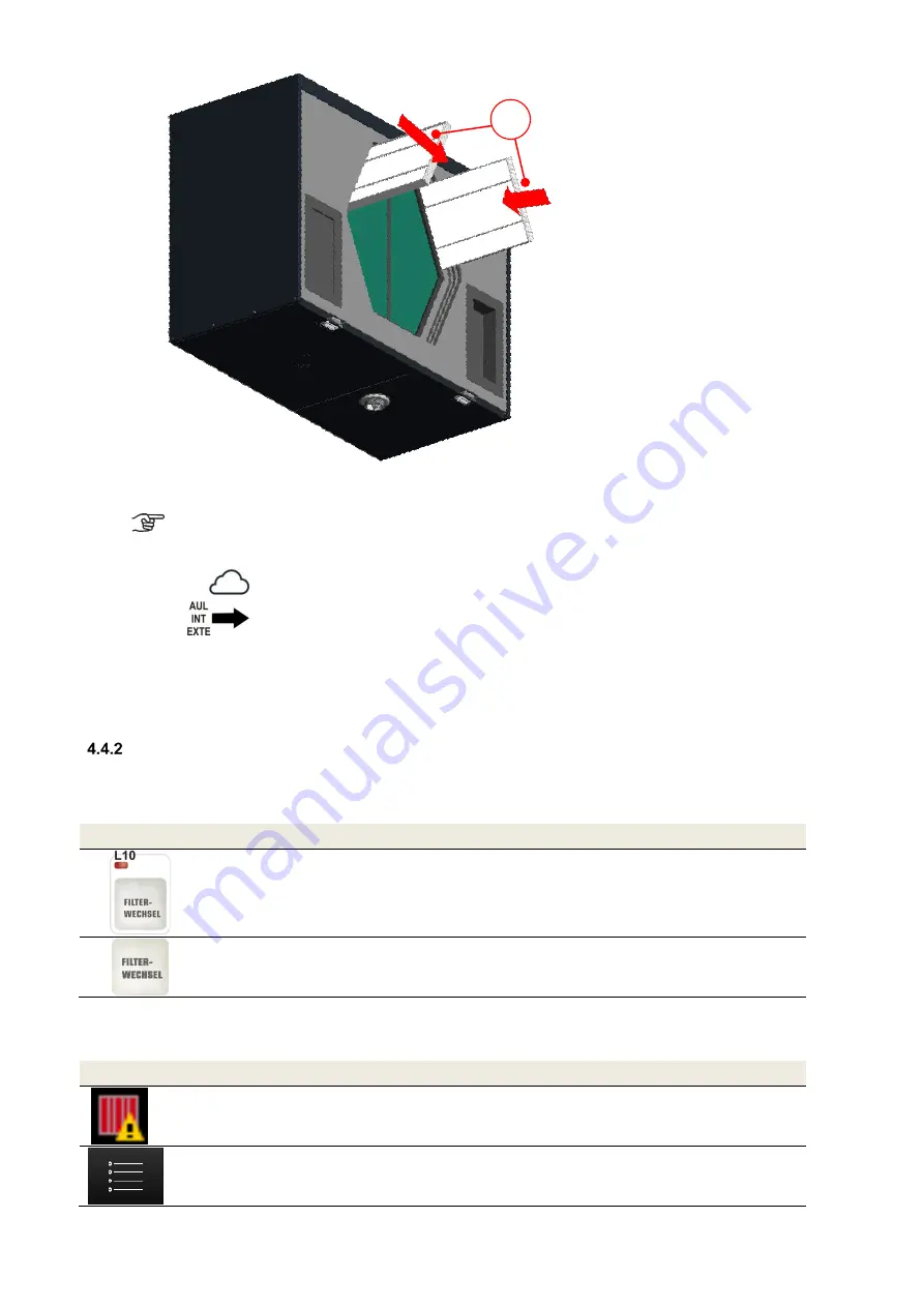
Fig. 13: Inserting the new filters according to the direction of flow
Depending on the unit type, filters with filter class ISO ePM1 must be inserted into the filter
compartment of the outdoor air connector in accordance with the type label! The outdoor air
connector is indicated by the symbol
on the air connections sticker.
7. Attach the EPP foam cover to enclose the slide-in filter compartments and heat exchanger.
8. Hook the front panel into the lock seam of the housing. Then press it down onto the housing in the snap
fastener area until it engages in the snap fasteners.
9. Reconnect the unit to the mains.
Resetting the filter running time
After completing the filter replacement, the counter for the filter running time must be reset. The filter running time can
be reset with a programmed digital input signal or with each connected control unit.
4.4.2.1 Reset filter running time with LED control panel
Symbol
Description
Explanation/Actions
LED 10
Filter running time
signal
If LED 10 lights up, then the filter running time has expired and a filter
inspection must be carried out.
Key
Reset filter running
time
To reset the filter running time, press and hold this key for > 3
s. LED 10
goes out. The counter starts the set filter running time.
Table 17: Reset filter running time with LED control panel
4.4.2.2 Reset filter running time with TFT control panel
Symbol
Description
Explanation/Actions
Filter running time
expired signal
If the symbol appears then the filter running time has expired and a
filter inspection must be carried out.
Button
Menu mode
By touching the menu mode button, you access the main menu.
F
Содержание FOCUS 200 Base
Страница 1: ...Translation of the original instruction manual Heat Recovery Unit FOCUS F 200...
Страница 49: ...49 Dimensions Fig 43 Dimensional drawing FOCUS...
Страница 50: ...50 FOCUS circuit plan Fig 44 Terminal assignment circuit diagram FOCUS...
Страница 51: ...51 Master Controller terminal assignment Fig 45 Master Controller terminal assignment...


