background image


- 33 -


PATON

 ProTIG 

DC TIG/MMA


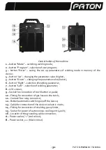
11.


The  user's  program  number  is  displayed,  switched  by  the 

button  «

Program"  (

2

), 

the maximum number of saved programs is 10 units. 

12.


Description  of  the  actual  parameter  is  displayed.  Each  mode  has  its  own  set  of 

parameters, switched by the buttons "Right" (

7

) and "Left" (

6

). 

13.


The values and units of measurement of the selected parameter are displayed. The 

parameter value changes by the buttons "Up" (

4

) and "Down" (

5

).  

14.


Indicators of the machine status: 

«Т

»

 indicator of the temperature state of the most heated parts of the machine. The 

red color of the indicator signals overheating of the machine and it is necessary to wait until 
it cools down, after which the indicator will change color to green again; 

«W» 

indicator of the welding process. If the indicator has a blue color, it means that 

the welding process (pressed button on the torch) runs on, and in this case regulation of all 
parameters is not available. 

Warning!!!

  To start the  welding process  in  MMA mode,  after 

setting up the parameters, the 

button «

Enter" (

3

) should be pressed. 

«V» 

autonomous  cooling  unit  liquid  flow  indicator.  The  red  color  of  the  indicator 

means either lack of connection of the machine to the autonomous cooling unit, or lack of 
coolant flow. 

Warning!!!

 If the liquid flow indicator glows red, welding in TIG mode is not 

available. 
 

In  order  to  be  able  to  operate  the  device  with  TIG-torches  with  air  cooling  at  a 

welding current of up to 140 A, it is necessary to switch off the relay of the coolant flow. For 
this it is required to: 

1) switch off the device; 
2) press and hold the 

button «

Enter

» (

3

) switch on the device; 

3) hold the button "Enter" pressed until the  inscription 

«Cooler OFF»

 appears on the 

screen (8); 
4) Release the b

utton «

Enter

».


After that, the liquid flow indicator will change the color to blue. This means that now it is 
possible to use torch with air cooling. To switch on the  liquid flow relay, it is necessary to 
repeat  the  abovementioned  steps,  as  a  result  of  which 

the  inscription  «Cooler  ON» 

will 

appear on the screen. 

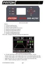
15.


The  cyclogram  of  selected  welding  mode  is  displayed,  for  each  mode  the 

cyglogram is different. 

16.


Indicator  of the selected mode  of  torch  button  operation: 

2Т, 4Т, 

or  PED (  pedal 

mode).  

17.


Indicator of pulsed mode:  

«Р» 

pulsed mode switched on; 

«N» 

pulsed mode switched off.   

18.


Indicator  of  saving  the  program  adjusted  by  the  user.  Displaying  the  letter  "S" 

signals that this program is saved into the memory of the device. 

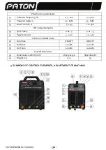
3.1 Symbols of all welding modes parameters  

1. 

«

Button mode

»


 mode of button on the torch: 

2Т/4Т/ PED

;   

2. 

«

Preflow

»


 time of preblowing by shielding gas; 

Содержание ProTIG-200

Страница 1: ......

Страница 2: ......

Страница 3: ...9 3 2 9 3 3 9 4 TIG AC DC 10 4 1 TIG AC 10 4 2 TIG DC 13 4 3 TIG Lift 16 4 4 Double Pulse 17 4 5 SPOT 17 4 6 TIG MIX 18 4 7 TIG AC TIG DC 18 4 8 18 5 MMA 19 5 1 19 5 2 20 6 21 6 1 21 6 2 21 6 3 21 6 4...

Страница 4: ...TIG MMA 1 PATON ProTIG 200 315 400V AC DC TIG AC DC TIG MIX AC DC SPOT AC DC TIG AC TIG DC SPOT 1 2 10 3 2 4 2 4 4 5 PULSE TIG AC DC MMA 6 TIG Lift Double Pulse Remote Control TIG 7 8 SPOT 9 10 11 12...

Страница 5: ...80 7 6 3 13 5 8 10 200 10 315 9 TIG DC 5 200 10 315 10 60 80 80 11 100 DC 126 180 12 40 DC 200 315 13 100 C 140 200 14 50 C 200 315 15 16 17 10 10 18 19 TIG AC DC MMA SPOT 20 TIG Lift 21 Double Pulse...

Страница 6: ...5 200 15 70 30 15 90 15 90 31 0 1 200 0 1 200 32 15 85 15 85 33 5 195 10 300 RIV 34 0 01 5 0 01 5 35 5 200 10 315 36 Anti Stick ON OFF ON OFF 37 Hot Start 1 100 0 100 38 Arc Force 1 100 0 100 39 465 1...

Страница 7: ...PATON ProTIG DC TIG MMA 6 1 Mode 2 Program 3 Enter 4 Up 5 Down 6 Right 7 Left 8 LCD 9 10 11 12 13 14 15 400 16 B...

Страница 8: ...7 PATON ProTIG DC TIG MMA 1 2 3 4 5 6 7 LCD 1 Mode TIG AC TIG DC...

Страница 9: ...PATON ProTIG DC TIG MMA 8 SPOT 2 Program 2 10 3 Right 7 Left 6 4 Up 4 Down 5 5 W Enter 3 V 11 TIG TIG 140 1 2 Enter 3 3 Enter 8 Cooler OFF 4 Enter Cooler ON 6 7 2 4 PED 8 N...

Страница 10: ...9 PATON ProTIG DC TIG MMA 9 S 3 1 1 2 4 PED 2 3 4 5 6 7 8 9 10 11 12 13 14 15 REMOTE CONTROL 16 TIG Lift TIG 17 18 SPOT 19 SPOT 20 SPOT 21 AC DC 22 23 24 3 2 Program 2 Reset done 3 3 Mode 1...

Страница 11: ...PATON ProTIG DC TIG MMA 10 Mode 1 Right 6 Left 7 Mode 1 4 TIG AC DC TIG AC DC 10 9 14 12 Mode 1 TIG AC TIG DC 4 1 TIG AC zk zk F...

Страница 12: ...11 PATON ProTIG DC TIG MMA F 20 200 2 TIG C 2T TIG 2 2...

Страница 13: ...PATON ProTIG DC TIG MMA 12 4 TIG C 4T 4 2 TIG 2T pulse...

Страница 14: ...13 PATON ProTIG DC TIG MMA 4 TIG 2T pulse TIG C 1 2 2 2 3 30 4 1 5 100 6 1 7 30 8 5 9 50 10 150 11 50 12 50 13 50 14 8 50 100 150 1 4 2 TIG DC...

Страница 15: ...PATON ProTIG DC TIG MMA 14 zk zk F 2 TIG DC 2T TIG 2 2...

Страница 16: ...15 PATON ProTIG DC TIG MMA 4 TIG DC 4T 4 2 TIG D 2T pulse...

Страница 17: ...PATON ProTIG DC TIG MMA 16 4 TIG D 4T pulse TIG DC 1 2 2 2 3 30 4 1 5 100 6 1 7 30 8 5 9 50 10 50 11 50 12 8 50 100 50 1 4 3 TIG Lift...

Страница 18: ...17 PATON ProTIG DC TIG MMA TIG Lift 4 4 Double Pulse TIG 4 5 SPOT SPOT TIG 2 1 0 1 3 2 DC 1 100 0 1 3 2...

Страница 19: ...PATON ProTIG DC TIG MMA 18 120 50 120 50 4 6 TIG MIX TIG AC 2 1 2 4 7 TIG AC TIG DC 9 10 14 12 Mode 1 TIG AC TIG DC PED 4 8 TIG 10...

Страница 20: ...19 PATON ProTIG DC TIG MMA REMOTE CONTROL ON BUTTON MODE PED TIG AC TIG DC S1 R1 10 5 MMA I Mode 1 Enter 5 1 F...

Страница 21: ...PATON ProTIG DC TIG MMA 20 pulse DC 1 100 2 50 3 50 4 50 5 ON 6 50 7 OFF 8 8 W 150 100 50 50 1 5 2...

Страница 22: ...21 PATON ProTIG DC TIG MMA 50 50 6 6 1 TIG 6 2 6 3 1 190 260 ProTIG 200 AC DC ProTIG 200 AC DC 300 2 380 400 ProTIG 315 400V AC DC 6 4...

Страница 23: ...PATON ProTIG DC TIG MMA 22 7 10 8 4 15150 69 5 5 9 10 ProTIG 200 AC DC ProTIG 315 400V AC DC 50 60 230 3 380 3 400 190 260 10 80 80 5 200 10 315 DC 5 40 5 100 200 126 315 180 6 3 13 5...

Страница 24: ...23 PATON ProTIG DC TIG MMA TIG AC DC 20 4 26 8 10 4 18 24 32 12 18 11 1 1 2 ABITIG ProTIG 200 AC DC ProTIG 315 400V AC DC 4 1 3 ABICOR BINZEL 3 1 4 1 5 ProTIG 200 AC DC 1 6 PATON 1 7 8 1 12...

Страница 25: ...PATON ProTIG DC TIG MMA 24...

Страница 26: ...25 PATON ProTIG DC TIG MMA 13 ProTIG 200 AC DC 2 ProTIG 315 400V AC DC 1 PATON...

Страница 27: ...PATON ProTIG DC TIG MMA 26...

Страница 28: ...ble Pulse function 41 4 5 SPOT welding mode 41 4 6 TIG MIX welding mode 42 4 7 Operation of the machine with the use of pedal in TIG AC and TIG DC modes 42 4 8 Function of remote control of welding cu...

Страница 29: ...of button operation on the torch 2 4 19 Pedal support for smooth welding current regulation 20 PULSE function in TIG AC DC and MMA modes 21 TIG Lift Double Pulse and Remote Control functions for argon...

Страница 30: ...eral parameters 15 Contactless arc ignition 16 Welding current indication 17 Memorizing modes 10 programs 10 programs 18 Arc burning stabilization 19 Pulse function in TIG AC DC MMA SPOT 20 TIG Lift f...

Страница 31: ...r current 5 195 10 300 RIV mode parameters 34 Spot time s 0 01 5 0 01 5 35 Peak current 5 200 10 315 Functions in mode 36 Anti Stick ON OFF ON OFF 37 Hot Start 1 100 0 100 38 Arc Force 1 100 0 100 Ove...

Страница 32: ...ht selection of welding parameter 7 button Left selection of welding parameter 8 LCD screen 9 Socket for connection of torch button or pedal 10 Fitting for connection of gas hose on the torch 11 Coola...

Страница 33: ...selection of welding parameter LCD screen designed to display welding mode parameters Basic indicators of machine display 10 Displaying welding mode switched with the button Mode may be TIG AC manual...

Страница 34: ...autonomous cooling unit or lack of coolant flow Warning If the liquid flow indicator glows red welding in TIG mode is not available In order to be able to operate the device with TIG torches with air...

Страница 35: ...tistick function for counteraction of electrode sticking 23 Hot start function of improving the electrode ignition 24 Arc force function of welding arc burning stabilization 3 2 Reset the machine to f...

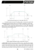
Страница 36: ...orch nozzle guaranteed protection before arc ignition starting current After preblowing the arc is ignited on the starting current and during Tp it rises to I and is used mainly for smooth heating of...

Страница 37: ...consider the operation of 2 stroke mode 2 stroke mode after pressing the button it is blown by shielding gas before welding and a smooth rise in the current to the specified value during Tp occurs Af...

Страница 38: ...t current will go down smoothly to the end current during the time Tc and will remain at this level until the button is pressed After releasing the button the arc will extinct and postblowing with the...

Страница 39: ...process will be poor After that welding can be started The value of actual welding current will range from 50A to 100 A with a periodicity of 150 oscillations per 1 second These parameters are set in...

Страница 40: ...e set current is gradually reduced to the end current over the time Tc after which its postblowing with shielding gas occurs Typical cyclogram of operation of 4 stroke mode TIG DC 4T 4 stroke mode aft...

Страница 41: ...onally depending on the welding conditions Typical cyclogram of operation of 2 stroke mode operation with pulse TIG D 2T pulse function Typical cyclogram of operation of 4 stroke mode operation with p...

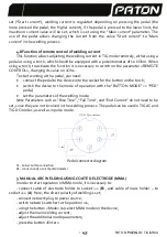
Страница 42: ...gnition or oscillator because it generates a powerful high frequency electric discharge at the moment of arc ignition If TIG Lift function is activated then the unit of contactless arc ignition will b...

Страница 43: ...similar welding process will be performed but on AC with a frequency of 120 Hz and 50 balance 4 6 TIG MIX welding mode This mode is mostly used for welding aluminum The essence of the mode is to comb...

Страница 44: ...g with a pedal you need connect the pedal to the device into the socket for the button on the torch switch the device to the mode of operation with the BUTTON MODE PED pedal set the parameters of the...

Страница 45: ...ic parameters as follows 1 Main current main welding current 100 2 Pulse balance balance of pulses shape 50 3 Pulse frequency 50 Hz 4 Low current pulsed mode 50 5 Antistick on 6 Hot start 50 7 Arc for...

Страница 46: ...r the losses caused by the use of the device not for the purpose The use according to the purpose involves compliance with the instructions of this manual 6 2 Requirement for placement The welding mac...

Страница 47: ...served and packed machine is stored in storage conditions 4 according to GOST 15150 69 for 5 years The unpreserved machine should be stored in dry closed rooms at air temperature not lower than plus 5...

Страница 48: ...erson causing damage to the machine or material values of the enterprise violation of the effective workflow All persons related to putting into operation control care and maintenance of the machine s...

Страница 49: ...equency current can negatively affect the serviceability of electrical appliances for example pacemaker Persons with such devices should consult with a doctor before approaching a working welding area...

Страница 50: ...cted the serviceability of the machine deformation of the casing and parts as a result of falling from a height or falling of heavy objects on the equipment loss of buttons and sockets with traces of...

Страница 51: ...seller reserves the right to refuse to provide warranty repair or set month and year of manufacture of the machine set by serial number as the date of commencement of warranty obligations when the cer...

Отзывы: