background image

Operator's Manual 

  DS 350 / 1334 

© PAT 

Rev. D 04/12/02  CSH 

190072_d.DOC 

40

6


PRE-OPERATION INSPECTION AND CALIBRATION VERIFICATION 

 
Before operating the crane, the following electrical connections must be checked to ensure that the system 
is properly connected for the crane configuration. 
 

Machines with only a Main Hoist 

 
If the crane works only with the boom and without boom extension, no additional connections are 
necessary. However, be sure the weight of the anti two-block switch is properly installed on the main 
hoist load line. With even parts of hoisting line, the weight shall be attached to the dead-end line. With odd 
parts of hoisting line, the weight shall be attached to the line of lowest speed. 
If the crane works with boom extension, the connecting cable shall be installed between the junction box 
on the boom extension and the boom junction box. The weight attached to the main hoist anti two-block 
switch shall be removed. In that case the anti two-block switch has to be locked with the red Anti Two-
Block Retainer, which is fixed with a red lanyard at the anti two-block switch (described on pages 40 and 
41). Then the weight shall be reattached to the boom extension anti two-block switch. 


Failure to re-position the anti two-block switch weight will prevent the over hoist system from 
functioning properly. No weight shall be on the main hoist anti two-block switch when the boom 
extension is being used. 


Machines with Main and Auxiliary Hoists 

 
If the boom extension is not in the operating position, the by-pass plug shall be installed in the main boom 
junction box. The weight of the main hoist anti two-block switch shall be installed. 
If the boom extension is in the operating position, the connecting cable shall be installed between the 
junction boxes on the boom extension and the main boom. Weights shall also be attached to the anti two-
block switches on both the main boom and boom extension.  
 
If the boom extension is in the operating position and no load line is being used on main boom, to prevent 
injury or damage to equipment, the weight shall be removed from main boom switch. In that case the anti 
two-block switch has to be locked with the red Anti Two-Block Retainer, which is fixed with a red lanyard 
(not shown) at the anti two-block switch. 
 

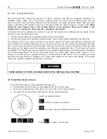
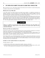
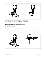
Installation of Anti Two-Block Retainer in Locking Position 

 
Procedure (see Fig. 1 and 2): 
 
1.


Pull the cable out of the switch and bend back parallel to the boom and hold (1). 

2.


Slide the retainer from left side with its slot over the cable between the crimped stop and the switch 
(2). Push it firmly straight onto the cable guide of the Anti Two-Block switch (3). 


Содержание 1334

Страница 1: ...www patamerica com PAT America Inc RATED CAPACITY LIMITER DS 350 1334 GRAPHIC for Lattice Boom Cranes OPERATOR S MANUAL P N 031 300 190 072 Rev D 04 12 02 ...

Страница 2: ......

Страница 3: ...s contained in this manual or for incidental or consequential damages in connection with the furnishing performance or use of this manual This document contains proprietary information which is protected by copyright All rights are reserved No part of this document may be photocopied reproduced or translated to another language without the prior written consent of PAT MANUAL REVISIONS REV DATE NAM...

Страница 4: ......

Страница 5: ...LER POSITION QUICK SELECTION 17 5 OPERATION 18 5 1 LIMIT SETTING 21 5 1 1 Radius Limitation 22 5 1 2 Tip Height Limitation 24 5 1 3 Boom Angle Limitation 26 5 1 4 Slewing Angle Limitation Virtual Wall Definition 28 5 2 INFO CRANE CONFIGURATION 38 5 3 DISPLAY CONTRAST CONTROL 39 6 PRE OPERATION INSPECTION AND CALIBRATION VERIFICATION 40 7 SERVICE AND MAINTENANCE 44 8 TROUBLESHOOTING 45 APPENDIX A D...

Страница 6: ......

Страница 7: ...ns and of over hoist conditions that could cause damage to equipment and personnel The device is not and shall not be a substitute for good operator judgment experience and use of accepted safe crane operating procedures The responsibility for the safe crane operation shall remain with the crane operator who shall ensure that all warnings and instructions supplied are fully understood and observed...

Страница 8: ... down will be stopped The fixed data regarding the crane such as capacity charts boom weights centers of gravity and dimensions are stored in memory chips in the central processor unit This data is the reference information used to calculate the operating conditions The boom angle is measured by the angle sensor mounted in the boom base The cable reel cable serves as an electrical conductor for th...

Страница 9: ...ation of the rigging states Next is the interactive input of the reeving Now the LC display shows in symbols all inputs and awaits acknowledgment or canceling Upon acknowledgment of the inputs the system is ready for operation 3 2 Operating Console The console has 3 functions inputs by the crane operator operating mode reeving input of geometry limit values and signalization of exceeded limit valu...

Страница 10: ...Operator s Manual DS 350 1334 PAT Rev D 04 12 02 CSH 190072_d DOC 4 3 3 Control Identification This unit contains a display and different controls which are described as follows Fig 2 Operator s Console ...

Страница 11: ...utton and Control Light CONTROL 12 Audible Alarm 13 By Pass Key Switch 14 Button and Control Light By Pass Anti Two Block 15 Button and Control Light By Pass LMI Kick out function F1 Button Function 1 F2 Button Function 2 F3 Button Function 3 F4 Button Function 4 1 LC Display The LC display visualizes graphical symbols texts and numerical values Depending on the selected operating mode setup limit...

Страница 12: ...nue his crane operation with extreme caution Alarm Light Anti 2 Block The red Anti Two Block Alarm Light 4 lights up when the anti two block limit switch contacts open indicating that a two blocking condition is approaching At the same time the audible alarm will sound The following crane movements will be stopped subsequently hoist up and boom down depending on your machine By Pass Key Warning Li...

Страница 13: ...ength Button LIMITS Button to start the function program limit values For the proceeding please refer to chapter 5 1 Button SELECT Button to start the function set operating mode For the proceeding please refer to chapter 4 1 The correct setting is of utmost importance for the proper function of the system and the crane Therefore only operators who are thoroughly familiar with use and operation of...

Страница 14: ...EY SWITCH 13 is turned to position B and the By pass A2B button 14 is pushed or The RCL kick out function is deactivated when the KEY SWITCH 13 is turned to position B and the By pass RCL button 15 is pushed KEY SWITCH 13 can be operated only by using the matching key Since button 14 and 15 deactivate the kick out function of the RCL system the anti two block system the following instructions must...

Страница 15: ... the anti two block switch is deactivated The By Pass Warning Light 5 flashes to indicate that the kick out function is deactivated Button By pass RCL This button can be operated only if key switch 13 is turned to position B While pushing this button the control lever lockout function of the RCL is deactivated The By Pass Warning Light 5 flashes to indicate that the kick out function is deactivate...

Страница 16: ...s can be acknowledged by merely pressing one key provided that the crane configuration has not been modified During the programming procedure the Rated Capacity Prewarning Light 3 and the Rated Capacity Limit Light 2 will light up and the aggravating crane movements will be interrupted Note If a configuration is selected which is not available the display will indicate error code E04 In this case ...

Страница 17: ...e questions Setting the boom type configuration main boom nose operation fixed jib operation luffing jib operation if main boom nose operation or jib operation selected tube boom type angular boom type this selection screen only appears if both boom types are available on this crane main boom tip extension hammerhead hammerhead tip extension fixed jib luffing jib luffing jib fixed jib For detailed...

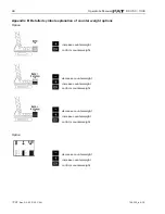
Страница 18: ... counterweight configuration Depending on the model of your crane and counterweight options please refer to Appendix B in this manual for detailed symbol explanation of counterweight decrease counterweight increase counterweight confirm counterweight OR increase counterweight confirm counterweight decrease counterweight increase counterweight confirm counterweight ...

Страница 19: ...ional lower counterweight without additional lower counterweight Specify boom jib lengths example luffing jib Select luffing jib length decrease luffing jib length increase luffing jib length confirm luffing jib length selection Select main boom length increase main boom length decrease main boom length confirm main boom length selection ...

Страница 20: ...ase reeving increase reeving confirm reeving Set 3rd hoist drum pick point select pick point 1 select pick point 2 no use of 3rd hoist drum Select 3rd hoist reeving decrease reeving increase reeving confirm reeving Once you have set the pick points you can switch between them by selecting which hoist drum is in use Select hoist in use example luffing jib Hoist in use selection use pick point 1 as ...

Страница 21: ...dure At the end of the procedure all selections are represented once again in symbolic forms If selections have been made the corresponding symbols are filled black i e hoist drums Hoist in use quick selection chapter 4 2 crawler position quick selection chapter 4 3 cancel procedure confirm inputs ...

Страница 22: ...tered without having to go through the whole RCL setup procedure again Call RCL setup procedure F1 F2 F3 F4 Directly call function Hoist in use quick selection Select hoist in use example use pick point 1 as defined use pick point 2 as defined F2 F3 F4 Confirm modification call up the function again if you have selected the wrong hoist drum by mistake Note If a configuration is selected which is n...

Страница 23: ...ctly without having to go through the whole RCL programming procedure again Call RCL Programming Procedure F1 F2 F3 F4 Directly call function Crawler Position Quick Selection input of crawler position retracted crawlers extended crawlers F2 F3 F4 Confirm modification select again the function if you made a wrong selection Note If a configuration is selected which is not available on the present cr...

Страница 24: ...ample shows a typical operating screen for a crane with a main boom or main boom with fixed jib configuration Please note that the crane symbol does not reflect the crane configuration that has been selected To see the selected crane configuration push the INFO Button Please refer to chapter 5 2 tip height max load additional text information if required actual load radius main boom angle operatio...

Страница 25: ...s a typical operating screen for luffing jib configuration Please note that the crane symbol does not reflect the crane configuration that has been selected To see the selected crane configuration push the INFO Button Please refer to chapter 5 2 tip height max load additionally text information if required actual load radius main boom angle Luffing jib angle operation code utilization bargraph ree...

Страница 26: ...imits exceeded see chapter 5 1 1 a Symbol Virtual Wall continuously visible Virtual Wall active blinking Virtual Wall limits exceeded see chapter 5 1 1 b Symbol height limitation continuously visible height limitation active blinking height limit exceeded see chapter 5 1 2 Symbol boom angle limitation continuously visible boom angle limitation active blinking Boom angle limits exceeded see chapter...

Страница 27: ...ally or in combinations Exceeding a programmed limit triggers an audible and visual alarm Depending on the crane type not all functions listed below may be available The functions provide an audio visual alarm when set limits are reached They do not provide any function kick outs Overview limits Radius Limitation chapter 5 1 1 Tip Height Limitation chapter 5 1 2 Boom Angle Limitation chapter 5 1 3...

Страница 28: ...ct the corresponding symbol to call the function Radius Limitation Screen will now show You have the choice to Set a minimum radius limit Set a maximum radius limit Exit the function without any changes If a limit has already been set it will be shown as blacked out area with the set value s for radius limit You have the choice to Change the minimum radius limit Change the maximum radius limit Exi...

Страница 29: ...mum radius limit there will be no left black bar and no radius value displayed Pushing will accept setting and quit function  To set delete maximum radius limit Screen shows with current radius value To set To delete Position boom at the desired maximum radius Push to set current working radius as maximum radius limit Push to delete maximum radius limit and exit the function This takes you back t...

Страница 30: ...all LIMIT Setting Select the corresponding symbol to select function Tip Height Limitation Screen will now show You have the choice to Set a tip height limit Exit the function without any changes If a limit has already been set it will be shown as blacked out area with the set value for tip height limit You have the choice to Change the tip height limit Exit the function without any changes Delete...

Страница 31: ...rrent tip height as tip height limit Push to delete tip height limit and exit the function This takes you back to the previous screen Set Delete Tip Height Limits Screen now shows symbol with a black bar and the set tip height limit value if you have set one If you did not set a tip height limit there will be no black bar and no tip height value displayed Pushing will accept setting and quit funct...

Страница 32: ...nding symbol to call the function Boom Angle Limitation Screen will now show You have the choice to Set a maximum upper boom angle limit Set a minimum lower boom angle limit Exit the function without any changes If a limit has already been set it will be shown as blacked out area with the set value s for radius limit You have the choice to Set a maximum upper boom angle limit Set a minimum lower b...

Страница 33: ...ere will be no upper left black bar and no boom angle value displayed Pushing will accept setting and quit function  To set delete minimum lower boom angle limit Screen shows with current boom angle value To set To delete Position boom at the desired minimum boom angle Push to set current boom angle as minimum boom angle limit Push to delete minimum boom angle limit and exit the function This tak...

Страница 34: ...nd or right slewing angle or virtual wall definition  To call function Call LIMIT Setting Select the corresponding symbol to call the slewing limit functions Slewing Angle Limitation or Virtual Wall Now select one of the following Function Slewing Angle Limitation to set a minimum maximum slewing angle chapter 5 1 1 A Function Virtual Wall to set a Virtual Wall chapter 5 1 1 B ...

Страница 35: ...ngle limits Screen will now show no slewing limits set yet You have the choice to Set a left slewing angle limit Set a right slewing angle limit Exit the function without any changes If limits have been set already they will be shown as a blacked out area with the set values for left and right slewing angle limit You have the choice to Change the left slewing angle limit Change the right slewing a...

Страница 36: ...ng angle Push to set current slewing angle as left slewing angle limit Push to delete left slewing angle limit and exit the function This takes you back to the previous screen Set Delete Slewing Angle Limits Screen now shows symbol again with the set slewing angle value for left slewing angle limit if you have set one Pushing will accept setting and quit function Pushing will delete limits and qui...

Страница 37: ...e limit Push to delete right slewing angle limit and exit the function This takes you back to the previous screen Set Delete Slewing Angle Limits Screen now shows symbol with a blacked out area and the set values for slewing angle limit if you have set them If you did not set a slewing angle limits there will be no black area and no slewing angle values displayed Pushing will accept setting and qu...

Страница 38: ...cle The wall is defined by a straight line between two set points and then can be trimmed by positioning the boom tip at a point near the wall and removing part of the wall to the left or right of the boom After the walls have been set the system alerts the operator when the boom approaches them This is done both visual and audible The console will warn the operator by an audible beeping alarm whi...

Страница 39: ...ting screen Sets a point in the working area to start a wall Having pressed SET the X is displayed without blinking at this point Move the boom to the second point at a safe distance from the obstacle This point should be the maximum distance from the first point that can be safely reached by the boom tip The blinking X at the boom tip indicates that the second point may be set to define the wall ...

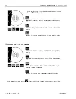
Страница 40: ...all creation screen Accepts the defined wall and enters the wall editing screen  VIRTUAL WALL EDITING SCREEN Deletes all virtual wall settings and returns to the operating screen Deletes existing wall and returns to the virtual wall creation screen Allows the operator to edit the virtual wall by trimming or creating a corner in the wall Accepts the defined walls and exits to operating screen Afte...

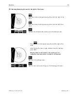
Страница 41: ...the wall to the left of the boom Accepts the defined walls and returns to the editing screen Press to trimming removing the wall the right of the boom After moving the boom to safe distance from the obstacle press SET Warning Never work outside a safe working area as outlined by common practice standards and manuals Returns to the editing screen Sets the trim position and brings up the following e...

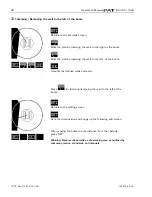
Страница 42: ...Edits the wall by trimming the wall to the left of the boom Accepts the defined walls and exits Press for trimming removing the wall to the left of the boom Returns to the editing screen Sets the trim position and brings up the following edit screen After moving the boom to safe distance from the obstacle press SET Warning Never work outside a safe working area as outlined by common practice stand...

Страница 43: ...al wall settings and returns to the operating screen Deletes existing wall and returns to the virtual wall creation screen Allows the operator to edit the virtual wall by trimming or creating a corner in the wall Accepts the defined walls and exits to operating screen ...

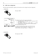
Страница 44: ...he crane symbol representing the selected boom configuration here main boom 100 ft plus luffing jib 60 ft the adjusted configuration marked black i e counter weight selection hoist drum selection and track position and the extended operating code To confirm the hoist selection please use the function set operating mode button SELECT chapter 4 1 plus the function Hoist in use quick selection chapte...

Страница 45: ...rast adjustment Press CTRL A pattern is shown which helps setting the display to the optimum contrast Use the functional keys to modify the contrast upon request darken display brighten display confirm setting Press key OK to store the momentarily adjusted contrast value and to quit the function During normal RCL operation the display contrast can be adjusted too by pressing button F2 darken displ...

Страница 46: ...to re position the anti two block switch weight will prevent the over hoist system from functioning properly No weight shall be on the main hoist anti two block switch when the boom extension is being used Machines with Main and Auxiliary Hoists If the boom extension is not in the operating position the by pass plug shall be installed in the main boom junction box The weight of the main hoist anti...

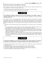
Страница 47: ...est visibility for the operator 5 Removal and Storage of the Anti Two Block Retainer Procedure see Fig 3 and 4 1 Pull the cable out of the switch 1 and bend back parallel to the boom and hold 2 2 Move the retainer down 3 and then left 4 to remove it from the Anti Two Block switch Release the cable 3 For storage slide the retainer from right side 5 over the Anti Two Block switch until the clips A l...

Страница 48: ...ti two block switches When the weight is lifted the audible alarm 12 should sound the anti two block alarm light 4 should light b Slowly raise the main boom load handling device to create a potential two block condition When the load handling device lifts the weight the audible alarm 12 should sound the anti two block alarm light 4 should light and the motion of the load handling device should be ...

Страница 49: ...ayed on the RCL Rated loads include the weight of the hook block slings and auxiliary load handling devices Their combined weights shall be subtracted from the listed load capacities as stated on the load capacity chart to obtain the net load to be lifted If any of the displays reflects a deviation between displayed and actual values an authorized PAT service representative shall be called for rep...

Страница 50: ...ystem If electrical wiring is damaged it shall be replaced immediately 2 If the insulation is worn on the electrical wiring or cable guides are damaged these parts shall be replaced 3 Check the anti two block limit switches for freedom of movement Other than correcting the problems identified in the Malfunctions Table and replacing faulty mechanical parts and cables no other repairs shall be perfo...

Страница 51: ... be taken to correct the fault Faults within the electronic microprocessor shall be repaired by factory trained service personnel When these faults occur the competent service organization shall be contacted Malfunction Table Error Code Error E01 Fallen below the radius or above angle range E02 Radius range exceeded or fallen below angle range E03 Boom position is out of the permissible working ar...

Страница 52: ...wn to a radius or angle given in the load capacity chart E02 The maximum radius or minimum angle given in the load capacity chart was exceeded due to luffing down the boom too far Boom up to a radius or angle given in the load capacity chart E03 Boom position is out of the permissible working area over front Move boom back to the permissible working area See lifting diagram in the load capacity ch...

Страница 53: ...A Detailed symbol explanation of boom extensions main boom Tube or Angular Boom Fixed jib operation main boom with tip extension Horse Head luffing jib operation main boom with hammerhead luffing jib fixed jib operation main boom with hammerhead and extension ...

Страница 54: ...xplanation of counter weight options Option increase counterweight confirm counterweight decrease counterweight increase counterweight confirm counterweight decrease counterweight increase counterweight confirm counterweight Option decrease counterweight increase counterweight confirm counterweight ...

Отзывы: