System Description
© PAT
Rev. D 04/12/02 CSH
190072_d.DOC
5
1. LC Display Area
2. Load Moment Limit Light
3. Load Moment Prewarning Light
4. Alarm Light “Anti-Two-Block”
5. By-Pass Warning Light
6. Button “Alarm Stop”
7. Button and Control Light “TARE”
8. Button and Control Light “LIMITS”
9. Button and Control Light “SELECT
OPERATION MODE”
10. Button and Control Light "INFO"
11. Button and Control Light
"CONTROL"
12. Audible Alarm
13. By-Pass Key Switch
14. Button and Control Light "By-Pass
Anti-Two-Block"
15. Button and Control Light "By-Pass
LMI Kick-out function"
F1. Button "Function 1"
F2. Button "Function 2"
F3. Button "Function 3"
F4. Button "Function 4"
1
LC-Display
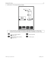
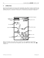
The LC display visualizes graphical symbols, texts and numerical values.
Depending on the selected operating mode (setup, limit mode or RCL
representation), the corresponding information is indicated on the display.
Please refer to the description of the different operating modes for the


