Parker Hannifin S.p.A S.B.C. Division
SLVDN User’s Manual
Page 131 of 181
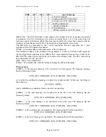
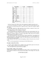
The first 4 bits (b0..b3) of the first byte in each instruction contain the instruction code.
In the first 8 instructions in the table (LD… ORN) and the SET and RES instructions, the
remaining 4 bit of the first byte (b4..b7) contain the value y, while the second byte contains
the value Pa.
In the ADD, SUB, MUL e DIV instructions, the second byte contains the value Pa, the
third byte the value Pb, and the fourth byte the value Pc.
In the END instruction, the second byte is not used.
In the FIN instruction, the fifth bit (b4) of the first byte selects the parameter: b4=0 if it
refers to Pb40, b4=1 if it refers to Pb150; the sixth bit (b5) of the first byte is used for logical
negation: b5=0 the bit is copied, b5=1 the bit is negated before being copied. The second byte
of the FIN instruction contains the value of y.
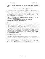
If the FIN instructions are used, they must be the first instructions of the program and
cannot be more than 2. They occupy the addressed from 0h to 3h. If a FIN instruction is
inserted beginning at the 4h address or after any other instruction, the FIN instruction does
not function and is ignored (NOP).
The instructions must follow each other beginning at address 0h and no byte can be left
empty.
There is only one program and it is terminated with the END instruction.
Examples of using the serial line
In order to better understand how to implement the communication protocol on the serial
line, some examples of each type of message are given below.
The values indicated are only indicative as examples.
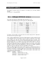
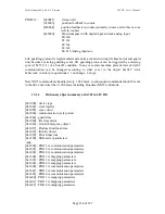
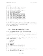
First example: reading a 1 byte parameter
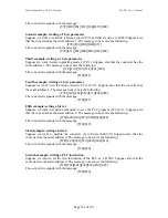
Suppose we want to read the value of the parameter Pr25 (release software) and that its value
is 43. Suppose also that the converter has the serial address 0. The message to be sent is the
following.
[$7E][$80][$01][$32][$B3]
Instruction
Code
Length (bytes)
LD Pa.y
0
2
LDN Pa.y
1
2
OUT Pa.y
2
2
OUTN Pa.y
3
2
AND Pa.y
4
2
ANDN Pa.y
5
2
OR Pa.y
6
2
ORN Pa.y
7
2
ADD Pa, Pb, Pc
8
4
SUB Pa, Pb, Pc
9
4
MUL Pa, Pb, Pc
10
4
DIV Pa, Pb, Pc
11
4
SET Pa.y
12
2
RES Pa.y
13
2
FIN Pb40.y/Pb150.y
14
2
END
15
2
Содержание SLVD1N
Страница 7: ...Parker Hannifin S p A S B C Division SLVDN User s Manual Page 7 of 181 ...
Страница 22: ...Parker Hannifin S p A S B C Division SLVDN User s Manual Page 22 of 181 ...
Страница 23: ...Parker Hannifin S p A S B C Division SLVDN User s Manual Page 23 of 181 ...
Страница 34: ...Parker Hannifin S p A S B C Division SLVDN User s Manual Page 34 of 181 5 6 Motor connection diagrams ...
Страница 35: ...Parker Hannifin S p A S B C Division SLVDN User s Manual Page 35 of 181 5 7 Resolver connection diagrams ...
Страница 36: ...Parker Hannifin S p A S B C Division SLVDN User s Manual Page 36 of 181 5 8 Encoder connection ...
Страница 181: ......


