


Parker Hannifin S.p.A. - S.B.C. Division HPD N User’s Manual
66
In certain cases a more precise axis zero reference is required; this is achieved using, in
addition to the proximity sensor on the machine, also the motor position transducer. In this
setup the proximity sensor signal is correlated with the first zero on the motor position
transducer.
The following example provides this functionality using operating mode (9) (trapezoidal
profile).
After setting default values, set up operating mode 9 (Pr31=9, b99.11=1, b40.2=0,
b40.12=1, and any other settings required) and then enter the zero proximity sensor homing
speed in Pr5.
Terminal 13 on X3 = homing pulse command.
Terminal 14 on X3 = PNP type axis zero proximity sensor.
Terminal 11 on X2 = digital output. Switches to 1 when the homing phase is terminated.
The following bits are utilised b91.8, b91.9, b91.11.
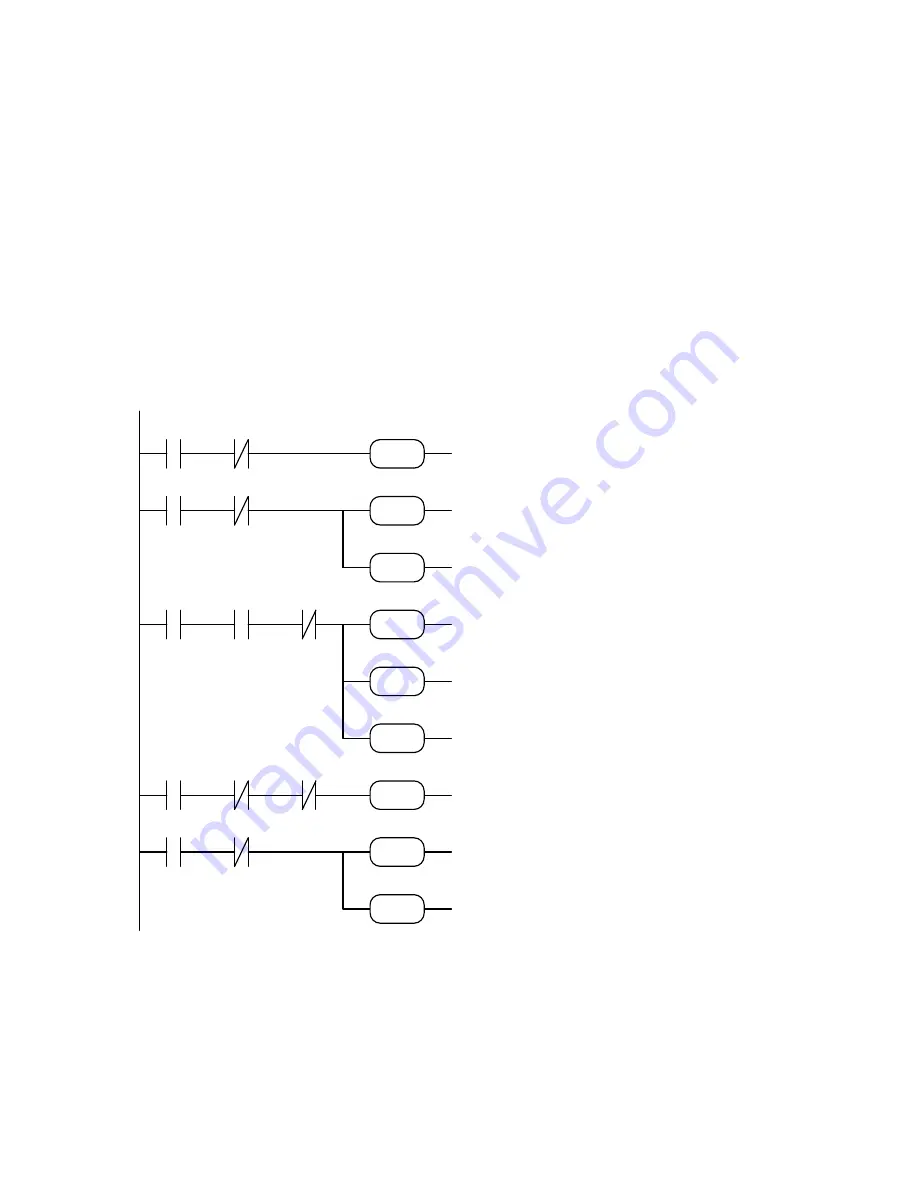
The program is as follows:
The precision of the positioning on the zero
resolver depends on the stability of the motor in the moment in which the trapezoidal profile
is calculated for final alignment. You must therefore make sure that the motor shaft has
stopped before this calculation. In the example above, the halted motor test is done with bit
b41.2. In this case, the imprecision is due to the fact that this bit has a precision of
±
1 rpm.
Should greater precision be required, in place of the test b41.2 set a sufficient delay to ensure
that the motor shaft has stopped.
LD
90.2
ANDN 91.9
RST 40.2
LD 90.3
ANDN 91.0
SET 91.9
SET 40.2
LD 91.9
AND 41.2
ANDN 91.8
SUB 79.28.64
SET 70.8
SET 91.8
LD 91.8
ANDN 70.8
ANDN 91.0
SET 91.0
LD 41.4
ANDN 91.11
SET 40.2
SET
91.11
If homing command is given
and not yet executed, disables
operating mode: the motor
runs at speed set in Pr5
when proximity sensor
operates alignment is enabled
on the resolver zero position
proximity sensor trip is
followed by trapezoidal
profile to align with resolver
zero position
if alignment with resolver
zero is terminated, sets axis
zero terminated output
if drive is OK operating mode
is enabled
RST
90.2
91.9
40.2
91.9
SET
40.2
SUB
79 28 64
SET
70.8
91.8
SET
90.3
91.0
91.9
91.8
70.8
SET
91.0
91.0
SET
91.8
41.2
SET
91.11
SET
41.4
91.11
40.2
Содержание HPD2N
Страница 1: ...HPD N HPD2N HPD5N HPD8N HPD16N HPD20N HPD24N User s manual rev 8 5 November 2004 software rel 41...
Страница 3: ......
Страница 4: ......
Страница 121: ...Parker Hannifin S p A S B C Division HPD N User s Manual 118...
Страница 125: ......