88
Gemini GV Hardware Installation Guide
Installation Guidelines
Gemini products are made available under “Restricted Distribution” for use in the
“Second Environment” as described in EN 61800-3: 1996, page 9.
Cabinet Mounting
For Electromagnetic Compatibility, cabinet mounting is not required. However,
Gemini drives have high voltage terminals—for safety purposes, the drive must
not be user accessible during normal operation.
Drive Mounting
The Gemini drive is designed to be mounted to an earthed metal panel. For EMC
performance, mount the mains filter to the same panel, as close to the drive as
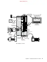
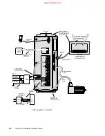
possible. See the EMC Installation drawing at the end of this appendix.
Cable Routing
Route high power cables (motor and mains) at right angles to low power cables
(communications and inputs/outputs). Never route high and low power cables
parallel to each other.
Cable Shielding
All cables must maintain high integrity 360 degree shielding. Compumotor CE
cables are fully shielded and provide the required screening. When you install
limit switches and other inputs/outputs, you must observe proper noise immunity
standards. See the EMC Installation drawing at the end of this appendix.
Ferrite Absorbers
Some installations may require that you take additional EMC measures. To further
increase product immunity and reduce product emissions, you may add clip-on
ferrite absorbers to all cables. Compumotor recommends a ferrite with at least
200 ohm impedance at 100 MHz, such as:
Steward Ferrite
part number 28A2024
Fair-Rite
part number 0443164151
(These ferrites are available from Compumotor, part number 47-015956-01)
Enclosure Mounting the Gemini Drive
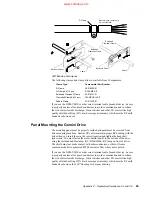
The enclosure must be properly earthed and paint must be removed from drive
mounting and RF earth bonding locations. Proper shield termination of all cables
entering and exiting the enclosure is required. The motor shield (braid) must be
fastened to the drive using the included saddle clamp or R-Clamp. The shield must
not make contact with other conductors, as this will cause common mode drive
generated PWM current to flow where not expected. The shields of all other cables
that enter or exit the enclosure must be RF bonded to the enclosure entrance point
via R-Clamp, bulkhead clamshell clamp, or other 360
°
bonding technique. This
ensures that no stray noise will enter or exit the enclosure. The next drawing
illustrates 360
°
bonding techniques.
www.comoso.com


