


62
Gemini GV Hardware Installation Guide
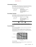
Enable Input (required)
To enable the drive and energize the motor, you must connect the enable input
(pin 1) to digital ground (pin 2). The next drawing shows the internal circuit.
Internal Connections
Same circuit design
as Enable
VINref
Enable
Digital Ground
Reset
26
1
2
3
DRIVE I/O Connector
+24V
6.81 K
Ω
10 K
Ω
20.0 K
Ω
18.2 K
Ω
12.0 K
Ω
33.0 K
Ω
33.0 K
Ω
-
+
Threshold
Sense
Inputs internally pulled up to
+24V, unless you connect an
external 5 – 24VDC supply to
the VINref terminal.
Input voltage range:
0
– 24VDC.
Switching Levels:
Low
≤
1/3 VINref voltage
High
≥
2/3 VINref voltage
Active Level:
Active low
Optional normally closed switch,
recommended for manual disable.
Enable Input and Reset Input
Reset Input (optional)
The reset and enable inputs use the same circuit design, as the drawing above
indicates.
To reset the drive, temporarily connect the reset input (pin 3) to digital ground
(pin 2). Reset begins when pin 3 is grounded. The drive will begin its power up
sequence upon disconnection of pin 3 from ground.
VINref – Voltage Input Reference (optional)
Use VINref (pin 26) to set the input reference voltage for the enable, reset, and
digital inputs.
It is not necessary for you to make connections to VINref. If you connect nothing,
then the enable, reset, and inputs are internally pulled up to +24VDC. This is the
factory default condition.
If you connect an external 5 – 24VDC power supply to VINref, then the input
switching thresholds become:
Low
≤
1/3
∗
VINref
High
≥
2/3
∗
VINref
(Default:, with VINref at in24VDC: Low < 8V; High > 16V)
www.comoso.com


