


Appendix D – EMC Installation Guidelines
65
motor cable is not within earthed conduit the entire length
of travel, the standard motor cable should not be used.
At the drive end of the motor cable, fit a ferrite absorber
over the cable before wiring to the motor connector (it
may be necessary to remove the existing connector).
Locate the absorber as close as possible to the connector
using heat-shrink sleeving.
For motors with exposed cabling (not within earthed
conduit), follow the guidelines below:
• Removable Cabling: Remove the motor cable from
the standard motor, and replace with a suitable cable
described below, see Motor Cables.
• Permanent Cabling: Cut off cable in excess of
approximately 4 inches (10 cm). Configure the motor
for series or parallel operation and attach a suitable
braided screen cable to the motor, see Motor Cables
below.
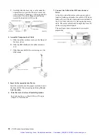
Termination of the braid shield at the motor must be made
using a 360° bond to the motor body, and this may be
achieved by using a suitable clamp. Many stepper motors
are designed to accommodate an appropriate terminal
gland which can be used for this purpose. If this is not the
case, P-clip the braid to the rear end bell of the motor
housing, as shown in Figure 4. This will not only provide a
good high-frequency bond, but strain relief as well.
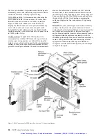
At the drive end, run the motor cable down to the
mounting panel, expose a short length of braiding and
anchor to the panel with a P-clip. The ZETA Series
require a safety earth connection to the motor (see green
and yellow striped wire in Figure 4) — take this from the
stud or bus bar. Run the safety earth lead alongside the
motor lead. Note that the motor cable should be kept away
from I/O cables carrying control signals.
Motor Cables
For 10 foot (replacement) cable lengths, use 4-core 1mm
2
(AWG 18) (SWG 20) braided screen cable for the motor
connections on the ZETA6xxx. At the drive end, fit a
ferrite absorber over the cable before wiring to the motor
connector. Locate the absorber as close as possible to the
connector using heat-shrink sleeving (use AWG 16 cable
for motors above 10 amperes).
All after-market motor connections must be made using a
high quality braided-screen cable. Cables using a
metallized plastic foil for an earth screen are unsuitable
and provide very little screening. Terminating to the
screen in a mechanically stable manner is difficult because
the screen itself is comparatively fragile — bending it in a
tight radius can seriously affect the screening performance.
There must be no break in the 360° coverage that the
screen provides around the cable conductors. If a
connector must be used it should retain the 360° coverage,
possibly by the use of an additional metallic casing where
it passes through the bulkhead of the enclosure. The cable
screen must not be connected to the cabinet at the point of
entry. Its function is to return high-frequency chopping
current back to the drive or controller. This may require
mounting the connector on a sub-panel insulated from the
main cabinet, or using a connector having an internal
screen which is insulated from the connector housing.
Within the cabinet itself, all the motor cables should lie in
the same trunking as far as possible. They must be kept
separate from any low-level control signal cables. This
applies particularly where the control cables are unscreened
and run close to the drive or other sources of electrical noise.
Motor Feedback Cables
Feedback devices such as encoders, tachometers and Hall
effect sensors also require the use of high-quality braided
screen cable. If it is necessary to replace the standard
feedback cable, select a braided screen cable that matches
the gage of the devices original cable and attach as close
to the transducer as possible. Avoid complex and bulky
connections that can cause degradation in feedback signal
quality. If possible, use in-line cable splicing techniques,
and cover the splice point with heat-shrink tubing. Remove
a section of the braided shield cable’s insulation to expose
the braid, and tie the braid to earth using the same P-clip
360° bond as shown in Figure 2. Differential signals
should use twisted pair cable to minimize magnetic
coupling. At the receiving end, fit a ferrite absorber over
the feedback cable before wiring the connector, then P-
clip the braid to a suitable ground (metal back-plane of
drive mounting panel, or earth point of device that
receives the feedback)— see Figure 3.
Step Motors
It is preferable to use motors with screw terminations
whenever possible. If flying-lead motors are used, it is
important that the unscreened leads are converted into a
braided-screen cable within 4 inches (10cm) of the motor
body. A separate terminal box may be used for this
purpose but the braided cable screen must be properly
strapped to the motor body, as shown in Figure 4. Motors
fitted with terminal boxes also allow local selection of
series or parallel connection, reducing the cost of the cable
running back to the drive.
Control Signal Connections
High-quality braided screen cable should be used for
control connections. In the case of the ZETA6xxx, which
has differential step-direction inputs, it is preferable to use
a cable with twisted pairs to minimize magnetic coupling.
No connection is made to the cable screen at the drive
itself. Fit a ferrite absorber close to the I/O connector and
run the cable down to the mounting panel as shown in
Figure 3. Expose a short length of the braided screen and
anchor to the panel with a P-clip.
Artisan Technology Group - Quality Instrumentation ... Guaranteed | (888) 88-SOURCE | www.artisantg.com