


Chapter 1. Installation
29
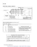
RP240
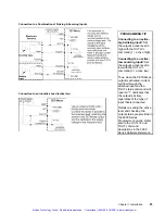
1. Cycle power to the ZETA6xxx.
2. If the RP240 is connected properly, the RP240’s status LED should be green and
one of the lines on the computer or terminal display should read
*RP24Ø
CONNECTED
.
If the RP240’s status LED is off, check to make sure the +5V connection is secure.
If the RP240’s status LED is green, but the message on the terminal reads
*NO
REMOTE PANEL
, the RP240 Rx and Tx lines are probably switched. Remove power
and correct.
3. Assuming you have not written a program to manipulate the RP240 display, the
RP240 screen should display the following:
COMPUMOTOR 6XXX INDEXER/DRIVE
RUN JOG STATUS DRIVE DISPLAY ETC
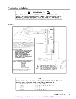
ASSUMPTIONS
• RP240 connected to
COM 2
•
COM 2
(PORT2) configured
for RP240. To verify, type
these commands:
PORT2
<cr>
DRPCHK
<cr>
The system response
should report “
*DRPCHK3
”.
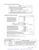
Pulse Cut
1. Open the P-CUT switch or turn off the device driving the P-CUT input.
2. Enter the
TINO
command (note the condition of the 6
th
bit from the left).
The response should be
*TINOØØØØ_ØØØØ
.
3. Close the P-CUT switch or turn on the device driving the P-CUT input.
4. Enter the
TINO
command.
The response should be
*TINOØØØØ_Ø1ØØ
.
TINO
response:
bit 6 = pulse cut input
bits 1-5, 7 & 8 are not used
Artisan Technology Group - Quality Instrumentation ... Guaranteed | (888) 88-SOURCE | www.artisantg.com