


28
ζ
ZETA6xxx Installation Guide
Connections
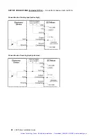
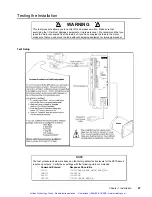
Test Procedure
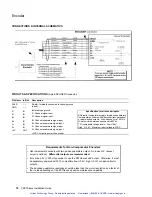
Response Format
(left to right)
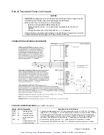
End-of-travel
and
Home Limits
NOTE: If you are not using end-of-travel limits, issue the Disable Limits (
LHØ
)
command and ignore the first two bits in each response field.
1. Enable the hardware end-of-travel limits with the
LH3
command.
2. Close the end-of-travel switches and open the home switch.
3. Enter the
TLIM
command. The response should be
*TLIM11Ø
.
4. Open the end-of-travel switches and close the home switch.
5. Enter the
TLIM
command. The response should be
*TLIMØØ1
.
6. Close the end-of-travel switches and open the home switch (return to original
config.).
7. Enter the
TLIM
command. The response should be
*TLIM11Ø
.
TLIM
response:
bit 1= POS (positive travel)
limit
bit 2= NEG (negative travel)
limit
bit 3 = HOM (home) limit
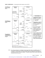
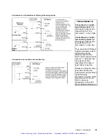
Motor and
Encoder
(motion)
1. Enter the
ENCØ
command to enable the motor step mode.
Enter the
PSETØ
command to set the motor position to zero.
Enter the
TPM
command to determine the motor position.
The response should be
*TPM+Ø
(motor is at position zero).
Enter the
D25ØØØ
command, followed by the
GO
command. The motor will move
one revolution (25000 steps) in the clockwise direction (viewed from the flange end).
Enter the
TPM
command to determine the motor position.
The response should be
*TPM+25ØØØ
(motor is at position 25000).
2. NOTE: Ignore this step if you are not using encoder feedback. This test assumes
you are using a 1000-line encoder yielding a 4000 count/rev resolution.
Enter the
ENC1
command to enable the encoder step mode.
Enter the
PSETØ
command to set the encoder position to zero.
Enter the
TPE
command to determine the encoder position. The response should be
*TPE+Ø
(encoder is at position zero).
If the encoder is coupled to the motor shaft: Enter the
D4ØØØ
command, followed
by the
GO
command. The encoder (and motor) will move one revolution (4000
counts) in the clockwise direction (viewed from the flange end).
If the encoder is not coupled to the motor shaft: Manually rotate the encoder
shaft one revolution in the clockwise direction (viewed from the flange end).
Enter the
TPE
command to determine the encoder position.
The response should
be
*TPE+4ØØØ
(encoder is at position 4000).
Enter the
ENCØ
command to return the ZETA6xxx to the default motor step mode.
TPM
response = motor counts
TPE
response = encoder
counts
Direction of rotation:
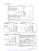
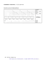
Programmable
Inputs
(incl. triggers)
1. Open the input switches or turn off the device driving the inputs.
2. Enter the
TIN
command.
The response should be
*TINØØØØ_ØØØØ_ØØØØ_ØØØØ_ØØ
.
3. Close the input switches or turn on the device driving the inputs.
4. Enter the
TIN
command.
The response should be
*TIN1111_1111_1111_1111_11
.
TIN
response:
bits 1-16 = prog. inputs 1-16
bits 17 & 18 = TRG-A & TRG-B
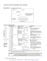
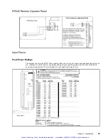
Programmable
Outputs
1. Enter the
OUTALL1,9,1
command to turn on (sink current on) all programmable
outputs. Verify that the device(s) connected to the outputs activated properly.
2. Enter the
TOUT
command.
The response should be
*TOUT1111_1111_1
.
3. Enter the
OUTALL1,9,Ø
command to turn off all programmable outputs. Verify that
the device(s) connected to the outputs de-activated properly.
4. Enter the
TOUT
command.
The response should be
*TOUTØØØØ_ØØØØ_Ø
.
TOUT
response:
bits 1-8 = prog. outputs 1-8
bit 9 = OUT-A
Artisan Technology Group - Quality Instrumentation ... Guaranteed | (888) 88-SOURCE | www.artisantg.com