


For more information about the Low Voltage Directive (LVD), see 73/23/EEC
and 93/68/EEC, published by the European Economic Community (EEC).
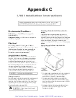
Environmental Conditions
Pollution Degree: The ZETA6xxx is designed for
pollution degree 2.
Installation Category: The ZETA6xxx is designed for
installation category II.
Electrical
Connecting & Disconnecting Power Mains
The ZETA6xxx’s protective earth connection is provided
through its make-first/break-last earth terminal on the
power mains connector. You must reliably earth the
ZETA6xxx’s protective earth connection.
Using an Isolation Transformer
The ZETA6xxx’s mains voltage is limited to 120 VAC
(240VAC for ZETA6104-240) nominal. If your mains
voltage is higher, use an isolation transformer located
between the power mains and the ZETA6xxx. Your
isolation transformer should be insulated to ~2300V rms.
Do not interrupt the protective earth conductor between
the source mains and the isolation transformer’s
secondary. The core of the isolation transformer and the
drive’s protective conductor terminal must both be
connected to the mains protective earth conductor.
CAUTION — Do not use an autotransformer.
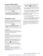
Adding Line Fuses
Line fuses need to be added to protect the transformer and
associated wiring. If the live wire cannot be readily
identified, fuse both phase conductors. The value of fuse
required is given by: (1.5 x VA)/(supply volts) [amps]
Fuse types should be anti-surge HBC.
WARNING —
Safety Ground (Earth Ground)
should never be fused.
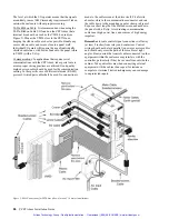
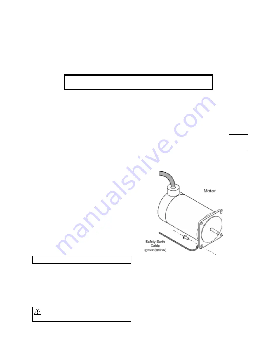
Providing a Protective Earth Connection for
Motors
You must provide a connection from the motor to a
reliable protective earth contact point. This connection
provides a protective earth for the motor, and is in addition
to the earth connection provided by the drain wire in the
motor’s power cable. The motor’s protective earth
connection is important for safety reasons, and must not be
omitted.
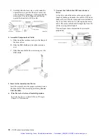
Make connections according to the diagram and
instructions below:
1. Use a spade lug in combination with a star washer and
mounting bolt to make good contact with the bare
metal surface of the motor’s mounting flange.
2. Use a green and yellow striped wire to make the
connection between the motor and earth. Wire gauge
must be no thinner than the current carrying wire in the
motor’s power cable.
3. Resistance between the motor and earth must be no
greater than 0.1
Ω
. Use thicker gauge wire if the
resistance is too high.
Appendix C
L V D I n s t a l l a t i o n I n s t r u c t i o n s
Artisan Technology Group - Quality Instrumentation ... Guaranteed | (888) 88-SOURCE | www.artisantg.com