Configuration
Machine zero mode
87
Unit
hardware
Connector
assignment / cable
Technical data
Configuration
Positioning and
control functions
Optimization
functions
Interfaces
Accessories /
options
Status
Parameter
Error list
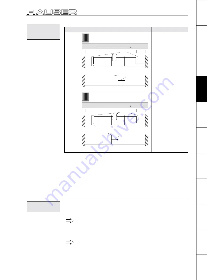
P212 ="8"
Find machine zero
Application
P213="0"
clockwise rotating motor
E2
P29 = 0°- 360°
position of actual MZ
signal MZ-ini.
E1
0°
360°
...
resolver zero
pulse
Linear movements.
No need for a machine
zero initiator.
Function
Travels during "Find
machine zero":
♦
to the relevant limit
switch.
♦
back to the 3rd
resolver zero pulse.
The 3rd resolver zero
pulse is evaluated as
machine zero.
P213="1"
clockwise rotating motor
E2
P29 = 0°- 360°
position of actual MZ
signal MZ-ini.
E1
0°
360°
...
resolver zero
pulse
Supplement
With P202, the distance
between initiator and
machine zero can be
increased (e. g. for large
gear ratios). Meaning:
P202=0 or 3; function as
described.
With P202>3, the
distance of the machine
zero can be moved by
further resolver zero
pulses.
P202 unit:
Resolver zero pulses =
motor revolutions
P217 ="1"
P216 = set correctly.
In the above diagram: P216="1": (limit switch E1 is approached with anti-clockwise
rotating motor)
The input of the machine zero initiator (X17/7) must be wired up with the relevant
limit switch:
P213="0": X17/8 must be connected to X17/7.
P213="1": X17/9 must be connected to X17/7.
P212="10": Teach machine zero
When activated via the command "Find machine zero" (Input I1&I2 or
command "POSA Home"), the current position of the motor is defined
as the machine zero.
A machine zero initiator is not required with this method.
Via parameter P29, machine zero can be moved from the teached point by up to
one motor revolution. The drive then executes machine zero travel from the current
position by the angle P29 in a clockwise direction.
Range of values for P29: 0...360 degrees (other values are considered as 0).
If P29=0, machine zero travel is not implemented.
Machine zero
equals a limit
switch
Condition:
Wiring up:
Teach machine
zero


