


6
Parker Hannifin
Pump & Motor Division Europe
Trollhättan, Sweden
Bypass Valves
Series BPV for F1 and T1 pumps
MSG30-8227-INST/UK/DE
Installation information
5
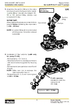
. Assemble the suction fitting to the valve
block as shown in the figure to the right A
’suction fitting’ consists of a straight, 45°,
90° or 135° suction fitting, clamps, cap
screws and O-ring.
IMPORTANT!
Always tighten the pressure connector (see
page 4)
before
tightening the cap screws
(to
20 – 25 Nm
).
NOTE
: A suction fitting kit is not included
with the pump; it must be ordered
separately
Suction
fitting
Clamps
Cap screws
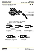
5
4
3
2
1
F1-25 restrictor
(included in drain line
connector kit
378 1640)
Tighten to
125 ± 15 Nm
Tighten to
20 to 25 Nm
UK
6
. Installation of flow restrictor
(valid only
for pump F1-25)
:
- Remove items 1, 2, 3 and 4
- Install items 5 and 4; carefully push down
until item 4 bottoms against the housing
seat
- Remove item 4 and push down item 5 until
it seats
NOTE:
Make sure not to damage the
housing seat for item 4
- Reinstall items 4, 3, 2 and 1 and tighten
to
125 ± 15 Nm
.