


3
Parker Hannifin
Pump & Motor Division Europe
Trollhättan, Sweden
Bypass Valves
Series BPV for F1 and T1 pumps
MSG30-8227-INST/UK/DE
Installation information
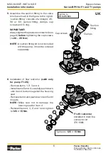
Pressure connector
tighten to:
BPV-F1-25 to -61
and T1-81:
50 ± 10 Nm
BPV-F1-81 to -101
and T1-121:
100 ± 10 Nm
IMPORTANT!
Always tighten the pressure
connector (see below)
before
tightening
the cap screws
(to
20–25 Nm
).
5
4
3
2
1
BPV_F1_split_ny.ai
Leif A./09-02-02
F1-25 restrictor
(included in drain
line connector kit
378 1640) See page
2 for installation.
BPV-F1 and -T1 bypass valves:
24 VDC solenoid is
standard
on F1-25/-41/-51/-61, F1-81/-101 and
T1-81/-121
12 VDC solenoid is optional
on F1-25/-41/-51/-61, F1-81/-101 and
T1-81/-121
Tighten to
8 ± 1 Nm
O-rings
O-rings
Tighten to
125 ± 15 Nm
Deutscher Text auf der Seite 7.
UK
‘Suction fitting’ (kit; not included)
IMPORTANT !
A drain line (not included)
must be installed
;
refer to information on page 2.
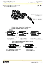
Drain line connector:
F1-25/-41/ -51/-61/-81/-101,
T1-81/-121: P/N 378 3039
(included with the bypass valve)
Plug (remove before installing the
drain line connector)
O-ring (included in ‘suction fitting’)
Tighten to
46 ± 3 Nm
Note: Remember to lubricate the
seal on the cartridge valve
before assembly in the valve
block.
Female connector included
(but
not
the cable)
(F1 end cap)