


14
Parker Hannifin
Pump & Motor Division Europe
Trollhättan, Sweden
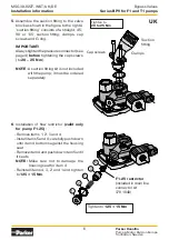
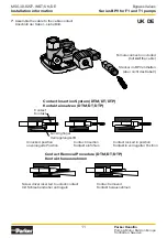
Bypass Valves
Series BPV for F1 and T1 pumps
MSG30-8227-INST/UK/DE
Installation information
Position notification regarding Machinery Directive 2006/42/
EC:
Products made by the Pump & Motor Division Europe (PMDE) of Parker Hannifin are
excluded from the scope of the machinery directive following the “Cetop” Position
Paper on the implementation of the Machinery Directive 2006/42/EC in the Fluid Power
Industry.
All PMDE products are designed and manufactured considering the basic as well as the
proven safety principles according to:
• ISO 13849-1:2015
• SS-EN ISO 4413:2010
so that the machines in which the products are incorporated meet the essential health
and safety requirements.
Confirmations for components to be proven component, e. g. for validation of hydraulic
systems, can only be provided after an analysis of the specific application, as the fact to
be a proven component mainly depends on the specific application.
Christian Jäger
General Manger
Pump & Motor Division Europe
Positionsmeldung zur Maschinenrichtlinie 2006/42/EG:
Produkte der Pump & Motor Division Europe (PMDE) von Parker Hannifin sind nach dem
Positionspapier „Cetop“ zur Umsetzung der Maschinenrichtlinie 2006/42/EG in der
Fluidtechnik vom Anwendungsbereich der Maschinenrichtlinie ausgenommen.
Alle PMDE-Produkte werden unter Berücksichtigung der grundlegenden und bewährten
Sicherheitsprinzipien nach folgenden Kriterien entwickelt und hergestellt:
• ISO 13849-1:2015
• SS-EN ISO 4413:2010
damit die Maschinen, in die die Produkte eingebaut werden, die grundlegenden Gesundheits-
und Sicherheitsanforderungen erfüllen.
Bestätigungen für Komponenten als bewährte Komponente, z.B. zur Validierung von
Hydrauliksystemen, können erst nach einer Analyse der spezifischen Anwendung erfolgen,
da die Tatsache, dass es sich um eine bewährte Komponente handelt, hauptsächlich von
der spezifischen Anwendung abhängt.
Christian Jäger
General Manager
Pump and Motor Division Europa