3
Installation Guide
AT-OME-RX31
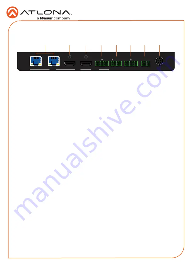
1
INPUT (HDBaseT)
Connect up to two category cables (CAT-5e or better) from each of these ports to a
compatible HDBaseT transmitter.
2
INPUT (HDMI)
Connect an HDMI cable from this port to a UHD/HD source.
3
OUTPUT (HDMI)
Connect an HDMI cable from this port to a display device.
4
OUTPUT (AUDIO)
Connect an audio output device to this port using the included 5-pin captive screw block.
Refer to
Audio Output Connector (page 4)
5
TRIGGER I/O
Connect voltage-controlled device to this port. A 4-pin captive screw connector is required.
Refer to
TRIGGER I/O Connector (page 5)
for wiring information.
6
RS-232
Connect the included 5-pin captive screw to this port to provide RS-232 control for the AT-
OME-RX31 and the connected display. Refer to
information.
7
RELAY
Connect the included 3-pin captive screw block to this port. This port provides a port,
which allows the control of screens, curtains, and other devices. Use a 48 V DC relay
with no more than 1 A current draw. Refer to
for wiring
information.
8
DC 24V
Connect the optional locking 24 V DC power supply to this power receptacle.
OMEGA
TM
AT-OME-RX31
FW
3
2
1
PWR
INPUT
IP MODE
RESET
LAN
SHOW IP
AT-OME-RX31
DC 24V
RELAY
COM C2
RX
C1
P
TX
TX RX
1
2
RS-232
TRIGGER I/O
-
+
L
R
-
-
+
+
OUTPUT
INPUT
3
2
1
Panel Descriptions
Rear
2
1
3
4
5
6
7
8


