background image

5

Installation Guide

AT-OME-RX31

The 

TRIGGER I/O

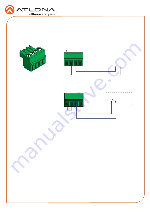
 port allows voltage-controlled devices, such as an occupancy sensor, to be 

connected to the AT-OME-RX31.  Use the included 4-pin captive screw connector to connect the 

device.  The voltage range is 3 V to 30 V DC.

TRIGGER I/O Connector 

1.  Use wire strippers to remove a portion of the cable jacket.
2.  Remove at least 3/16” (5 mm) of insulation from each of the wires.
3.  Insert the wires into correct terminal using the included 4-pin captive screw connector.
4.  Attach the 4-pin connector block to the 

TRIGGER I/O

 port on the AT-OME-RX31.

Common (Set LOW)

Control (Set HIGH)

Powered sensor

30 V (max.)

             -       +        P

Control (Set HIGH)

+12 V DC

Passive sensor

             -       +        P

Powered Sensor

Passive Sensor

Содержание Atlona AT-OME-RX31

Страница 1: ...and downscaling with frame rate conversion Additionally it provides integrated control for displays and room functions such as motorized screens and can be externally triggered with the addition of an...

Страница 2: ...lease this button next to the green LED indicator to switch the IP mode between DHCP and static IP modes The LED indicator will provide the current IP mode Refer to IP Configuration page 10 for more i...

Страница 3: ...R I O Connector page 5 for wiring information 6 RS 232 Connect the included 5 pin captive screw to this port to provide RS 232 control for the AT OME RX31 and the connected display Refer to RS 232 Con...

Страница 4: ...ced Balanced 1 Use wire strippers to remove a portion of the cable jacket 2 Remove at least 3 16 5 mm of insulation from each of the wires 3 Insert the wires into the correct terminals using the inclu...

Страница 5: ...V DC TRIGGER I O Connector 1 Use wire strippers to remove a portion of the cable jacket 2 Remove at least 3 16 5 mm of insulation from each of the wires 3 Insert the wires into correct terminal using...

Страница 6: ...shared between port 1 and port 2 NOTE Typical DB9 connectors use pin 2 for TX pin 3 for RX and pin 5 for ground On some devices functions of pins 2 and 3 are reversed RS 232 Connector 1 Use wire strip...

Страница 7: ...ed on or rebooted C1 and C2 are set to the Normally Open NO state RELAY Connector 1 Use wire strippers to remove a portion of the cable jacket 2 Remove at least 3 16 5 mm of insulation from each of th...

Страница 8: ...cable from the HDMI OUTPUT port to a display device 5 OPTIONAL Connect an audio output device to this port using the included captive screw block 6 OPTIONAL Connect a voltage controlled device such as...

Страница 9: ...the enclosure with one set of holes on the mounting bracket 3 Use the screws from Step 1 to attach the mounting bracket 4 Repeat steps 1 and 2 to attach the second mounting bracket to the opposite sid...

Страница 10: ...n the unit will use a self assigned IP address within the range of 169 254 xxx xxx Use an IP scanner along with the MAC address on the bottom of the unit to identify the unit on the network If a stati...

Страница 11: ...MS 2 0 web page then click the Login button 3 View the AT OME RX31 manual for more information AMS 2 0 Web GUI The AT OME RX31 includes a built in web GUI which allows easy management and control of a...

Страница 12: ...set to DHCP mode Refer to IP Configuration page 10 for more information Flashes green 2x Flashes four times to indicate that the unit is being set to DHCP mode Refer to IP Configuration page 10 for mo...

Отзывы: