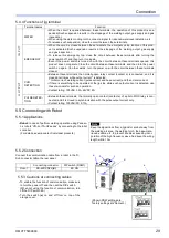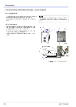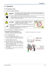
Connection
OMCTT5639E09
28
5.4 Connecting with jig(s)
5.4.1 Applications
When touching a printed circuit board, observe the following item to prevent
electrostatic destruction of the printed circuit board.
Before starting an operation, for example, touch any metal part of the case with your hand to
discharge static electricity
• To send out a command for the emergency stop or tem
-
porary stopping from a jig or a robot to this product.
• To provide a jig or a robot with the current detection sig
-
nal or pulse signal of this product, use the jig terminal.
Note
Keep the signal lines from a jig and/or a robot away from the
welding arc area, the welding torch, the base-material-side
cable, etc. to prevent troubles caused by incorporation of the
high frequency wave. And keep the wiring length within
10m.
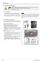
5.4.2 Position of jig terminal
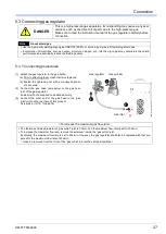
It is located
(e)
inside the product. (Loosen four crews
(a)
and two eyebolts
(b)
and then remove the top panel
(c)
.Åj
5.4.3 Cautions at wiring
(d)Wiring port (with grommet cover) (Rear
side):
Draw signal wires from jigs via this wire port.
* Make a cut in the grommet wall to insert it.
(f)Jumper:
When using a terminal with a short-circuit line
inserted, make sure to remove the short-circuit line from
that terminal. (Otherwise, that terminal does not work
properly.)
(g)Open terminals: Do
not use them.
• To these terminals, make sure to connect a no-voltage
contact signal or an open-collector transistor signal.
(Connecting a signal with voltage may cause a circuit
burnout to this product.)
• Between these terminals, the voltage of 15VDC is
applied when the circuit is open, and the current of DC
3mA is generated when the circuit is closed.
[Connect a signal not likely to cause any damage or con
-
tact failure under this voltage or current to these termi
-
nals.]
a
b
c
Front
Rear
e
d
f
g
Содержание YC-300BP2YAF
Страница 10: ...Rated Specifications OMCTT5639E09 10 2 2 1 Dimensions ...
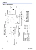
Страница 16: ...Installation OMCTT5639E09 16 Example of extension cable connection ...
Страница 49: ...Parts list OMCTT5639E09 49 9 Parts list ...
Страница 52: ...OMCTT5639E09 52 ...
Страница 53: ...Circuit diagram OMCTT5639E09 53 10 Circuit diagram NF9 NF8 ...
Страница 54: ...Circuit diagram OMCTT5639E09 54 10 1 Enlarged left half NF8 MCB ...
Страница 55: ...Circuit diagram OMCTT5639E09 55 10 2 Enlarged right half NF9 ...
Страница 62: ...OMCTT5639E09 62 ...
Страница 63: ...OMCTT5639E09 63 ...


