62
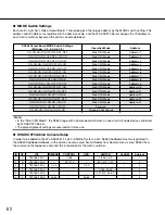
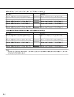
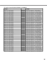
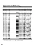
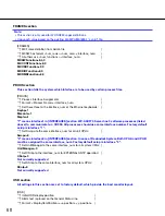
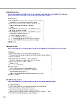
SX650 Output Board MODE Switch Settings
(Bit Order : 1-2-3-4-5-6-7-8)
●
MODE Switch Settings
Each matrix switcher's Video Output Board 1 should be given the unique address by the MODE switch setting. This
address and IP address are registered in the admin console, and the WV-ASC970 Server assigns the IP address to
each matrix switcher based on the admin console database.
Note:
• In the "Main CPU Mode", the SX650 cage with network board will work as one of switch node device controlled
by WV-ASC970 Server.
• The grayed (greyed) settings are reserved for future use.
●
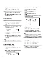
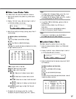
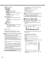
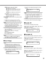
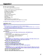
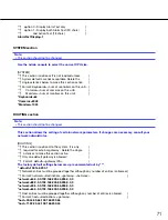
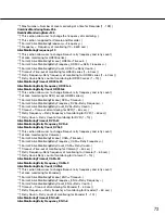
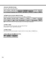
WV-ASC970 Admin Console Setup
In order to be added to the WJ-SX650 512 x 64 Full Matrix System, a WJ-SX650 SubNode must be registered in
the SX650 SubNode database. In the admin console, select Switch Nodes from Domain menu, select SX650 from
the sub-menu that appears, and enter the information for the matrix switcher.
ON-ON-ON-ON-OFF-OFF-OFF-OFF
Operation Mode
Main CPU Mode
Address
Address=1
ON-ON-ON-ON-OFF-OFF-OFF-ON
Main CPU Mode
Address=2
ON-ON-ON-ON-OFF-OFF-ON-OFF
Main CPU Mode
Address=3
ON-ON-ON-ON-OFF-OFF-ON-ON
Main CPU Mode
Address=4
ON-ON-ON-ON-OFF-ON-OFF-OFF
Main CPU Mode
Address=5
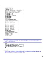
ON-ON-ON-ON-OFF-ON-OFF-ON
Main CPU Mode
ON-ON-ON-ON-OFF-ON-ON-OFF
Address=6
Main CPU Mode
Address=7
ON-ON-ON-ON-OFF-ON-ON-ON
Main CPU Mode
Address=8
ON-ON-ON-ON-ON-OFF-OFF-OFF
Main CPU Mode
Address=9
ON-ON-ON-ON-ON-OFF-OFF-ON
Main CPU Mode
Address=10
ON-ON-ON-ON-ON-OFF-ON-OFF
Main CPU Mode
Address=11
ON-ON-ON-ON-ON-OFF-ON-ON
Main CPU Mode
Address=12
ON-ON-ON-ON-ON-ON-OFF-OFF
Main CPU Mode
Address=13
ON-ON-ON-ON-ON-ON-OFF-ON
Main CPU Mode
Address=14
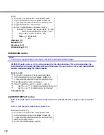
ON-ON-ON-ON-ON-ON-ON-OFF
Reserved
–
ON-ON-ON-ON-ON-ON-ON-ON
Standard SX650 Mode
–
ID
1
2
3
4
5
6
I/F
0
0
0
0
0
0
IPA
192.168.200.1
192.168.200.2
192.168.200.3
192.168.200.4
192.168.200.5
192.168.200.6
BRIDGE
–
–
1-32
–
–
33-64
CONTROL
1-256
257-512
–
–
–
–
OSD
–
–
1-32
–
–
33-64
SWITCH
1-256, 1-32
257-512, 1-32
–
1-256, 33-64
257-512, 33-64
–
ALARM
–
–
–
–
–
–
Address
1
2
3
4
5
6

