background image

26

 ●

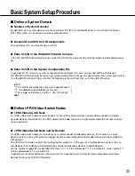
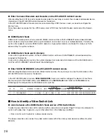
 Enter Cameras/Encoders and Decoders in the WV-ASC970 Admin Console

After deciding the Unit ID for each encoder and decoder, the next step is to enter the encoder and decoder device 
information in the WV-ASC970 Admin Console for the domain. 
In the WV-ASC970 Admin Console main menu and selecting i-PRO Devices screen, we need to configure the 
devices here.
Since these devices are part of the i-PRO node, select i-PRO from the Switch Nodes command on the Domain 
menu. 

 ●

 SX650 Switch Node

SX650 switch node consists of one more WJ-SX650 matrix switcher with WJ-PB65E01 network board. SX650 
switch node can only be located within a system domain, and cannot cross over multiple domains. Currently, the 
system only supports up to one SX650 switch node in a single system domain, and node ID is always set to its 
domain ID by the system software. 

 ●

 SX650 Switch Node and its Domain

In case of a single domain system, all the WJ-SX650 matrix switcher with WJ-PB65E01 network board will be 
assigned to that domain.
In case of a multiple domain system, the system designer has to decide which domain all the WJ-SX650 matrix 
switcher with WJ-PB65E01 network board should belong to.

 ●

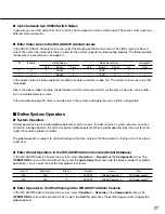
 Enter SX650 SUBNODES in the WV-ASC970 Admin Console

After deciding the domain ID for each WJ-SX650 matrix switcher, the next step is to enter the information in the 
WV-ASC970 Admin Console for the domain.

In the WV-ASC970 Admin Console,

 SX650 SUBNODES

 screen, we need to configure the devices. Since these 

devices are part of the SX650 node, select 

SX650

 from the 

Switch Nodes

 command on the 

Domain

 menu. 

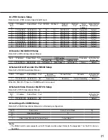
Following are the sample data for WJ-SX650 matrix switcher.

ID

I/F

IPA

BRIDGE CONTROL

OSD

SWITCH

ALARM

Address [MODE]

EA

Input

Output

5

6

7

8

1

1

192.168.200.1

1 - 256

1 - 32 1 - 256

1 - 32

OFF OFF OFF ON 00.00.00.00.00.00

 ■ 

How to Identify a Video Switch Link

 ●

 Links between a WJ-SX650 Switch Node and an i-PRO Switch Node

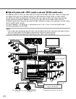
In order to pass video from one switch node to another, video links are required. Page 20 shows an example of a 
system with video links. In general, you can find video links in the following conditions:

  •  From a matrix switch output to a video encoder device.

The above video links can connect two video switch nodes within the same system domain or different system 
domains.  

Содержание WV-ASC970E

Страница 1: ...erate this product please read these instructions carefully and save this manual for future use The model number is abbreviated in some descriptions in this manual Operating Instructions PC Software Package Model No WV ASC970 WV ASC970E ...

Страница 2: ...HD616 WJ HD716 as i PRO Node 15 Support Camera Stream 1 or 2 15 Support Multicast Auto Start 16 Support Internet Mode Over HTTP 16 Support Third Party I O Ethernet Convertor 16 Support Audio Control for WV ASM970 16 Alive Monitoring 17 WJ ND400 Backup System 17 Priority Rules 17 Basic Rule 17 Operator Priority 17 Alarm Schedule and Operator Priority 17 Global Operator and Local Operator 17 Playbac...

Страница 3: ...ol 43 Operating Procedure 43 Camera Function Control 44 Camera Function Shortcut Function 44 Other Camera Functions 44 Running Sequence 45 Tour Sequence 45 Group Sequence 45 Call Group Preset 46 Monitor Display Control 47 On Screen Display Control 47 Alarm History Table 47 Alarm Status Table 48 Video Loss Status Table 48 System Status Table 48 Video Loss History Table 48 Multi Screen Segment Contr...

Страница 4: ...nd products contained in these operating instructions may be trademarks or regis tered trademarks of their respective owners Network Security As you will use this product connected to a network your attention is called to the following security risks 1 Leakage or theft of information through this product 2 Use of this product for illegal operations by persons with malicious intent 3 Interference w...

Страница 5: ...HD300 WJ HD300A WJ HD616 WJ HD716 WJ RT416 Series Operating Instructions Network Disk Recorder WJ ND200 WJ ND300 WJ ND400 WJ NV200 Series various Instructions Matrix Switcher WJ SX650 Series Operating Instructions Panasonic Network Cameras Instructions Network Interface Unit WJ NT304 WJ NT314 WJ GXE500 series Operating Instructions Network Video Decoder WJ GXD400 series Setup Instruction System Co...

Страница 6: ...ion Video Path A video path is a connection between video source and video destination which consists of one or more video links Server PC CPU Server PC is a Linux based server computer with WV ASC970 system software that manages all the system resources and system devices within a system domain It usually refers as a system domain computer Panasonic recommend using certain model number described ...

Страница 7: ...7 System A system is a collection of one or more system domains Area An area is an entity that groups together controllers and monitors ...

Страница 8: ...witch and Video Routing This function allows operators to switch video from one video source to another if the permission is granted For multiple operators competing for the same resource it only allows the highest priority operator to perform this func tion The next highest priority operator gains control when the highest priority operator releases the resource Here is a sample operation to switc...

Страница 9: ...er Control and Operation Global Recorder Selection Operators must seize a hard disk recorder and or network disk recorder in order to perform recorder operations After Global Video Switch and Video Routing refer to page 8 you can seize a recorder 200001 which means a recorder in domain 2 with a recorder ID of 1 Recorder Basic Operation The system provides operators with the following video recorde...

Страница 10: ...the instant playback operation for a seized global camera Global Tour Sequences Local Monitor Seize The system allows global operators to start and control a tour sequence from another system domain Before tour sequence operation a local monitor must be seized Here is the sample procedure to seize local monitor number 1 in domain 1 1 Login to System Controller Enter 500 for ID and enter 500 for pa...

Страница 11: ...ust be seized Be sure that the group sequence monitors are not seized by operators with higher priority Group Sequence Operation Group Sequence operations include start stop pause run next step and previous step Refer to p 45 Group Sequence Priority If another operator with higher priority has seized a Group Sequence monitor that monitor will maintain the original operator priority Note Group Sequ...

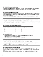
Страница 12: ...oad same global database to each domain Global Camera Numbering Setting Example Global Logical Camera Number Unit ID Local Logical Camera Number 2043 3 1 2044 2 2 2045 1 3 2046 3 3 Operation Example 1 Login to System Controller Enter 500 for ID and enter 500 for password Global Operator 2 Select monitor 1 Enter 1 and press MONITOR key 3 Select a global camera 2043 Enter 2043 and press CAMERA key 4...

Страница 13: ...clude Arm and disarm alarms Acknowledge active alarms Reset acknowledged or active alarms The system also supports automatically resetting and acknowledging alarms through configuration by the Admin Console Alarm Action The system supports the following alarm actions Camera spots both local and global Tour sequences both local and global Group sequence Text display Only WJ SX650 or WJ SX850 switch...

Страница 14: ... domain an administrator must enter the alarm information into the destination domain alarm database using its WV ASC970 Admin Console In the WV ASC970 Admin Console main menu select Records from the Alarm command on the Components menu For alarm Source select the source type Global Alarm and ID to 20001 in the above case Reset Exported Alarm Simultaneously In case that the Global Alarm Reset Sync...

Страница 15: ...sys ini file Also when the log size reaches approximately 500 KB the new file is created The Switch log takes all switching information between monitor and camera Time Synchronization The System Server can work as a stand alone time server for i PRO devices Refer to WV ASC970 Admin Console User s Guide to setup time server Support WJ HD616 WJ HD716 as i PRO Node The System Server can handle the WJ...

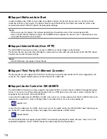
Страница 16: ...rtor The System Server can support the Third Party I O Ethernet Convertor and handle the I O alarm triggered by the convertor The support model numbers are described in the readme file Support Audio Control for WV ASM970 The WV ASM970 Version 3 0 or later supports the Audio ON OFF control for the WJ GXD400 through the System Server It can turn on or off the audio signal output from an i PRO device...

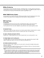
Страница 17: ...iority conflicts between operators the Server looks first at Operator priority then at Controller priority Alarm Schedule and Operator Priority Between alarm schedule and operator alarm carries the highest priority next is schedule and last is user Global Operator and Local Operator Only Global Operator can access other domain devices such as camera recorder and tour sequence Global Operator is ap...

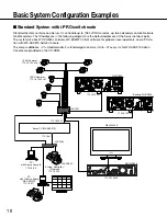
Страница 18: ...al or local operators and a PC sta tion with WV ASC970 Admin Console The sample database 01 standard adm standard gdm and sys ini file 01A sys ini for WV ASC970 Admin Console are provided on the CD ROM L3SW 1 172 16 192 1 172 16 192 21 172 16 192 22 i PRO Cameras 172 16 192 8 to 11 i PRO Cameras 172 16 192 4 to 7 WJ ND400 Backup WJ ND400 172 16 192 20 WJ GXD400 WV LW2200 WV CU950 PC with Admin Con...

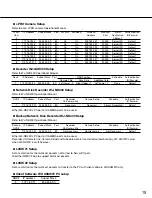
Страница 19: ...2 16 192 20 255 255 0 0 80 Left Lower 2 Right Upper 1 Left Lower 1 None Default Network Disk Recorder WJ ND400 Setup Refer to WJ ND400 Operational Manual DVR IP Address Subnet Mask Port Recorder Ch Camera link Camera Setup Schedule Authentication ID Passwd 1 172 16 192 21 255 255 0 0 80 Necessary Necessary Always Recording Default Either WJ ND400 s PC port or CAMERA port can be used Backup Network...

Страница 20: ...g happens frequently WJ NT304 has same behaviors Be sure to separate the analog switch node network from i PRO switch node network WJ SX650 WJ SX850 3 C 1 2 B 1 2 3 AC IN 3 2 1 A ALARM IN EXTENSION 3 IN EXTENSION 2 IN 4 3 2 1 DATA DATA 1 2 3 4 DATA 4 HDR4 TMNL8 HDR2 TMNL4 DATA 3 HDR3 TMNL7 HDR1 TMNL3 DATA 2 TMNL6 TMNL2 DATA 1 TMNL5 Video Output Board 2 Video Output Board 1 CAMERA IN ALARM OUT 2 AL...

Страница 21: ...D400 Operational Manual Dec IP Address Subnet Mask Port OSD Position Schedule Authentication ID Passwd Camera Title Time Date Additional Info 1 172 16 192 20 255 255 0 0 80 Left Lower 2 Right Upper 1 Left Lower 1 None Default Network Disk Recorder WJ ND400 Setup Refer to WJ ND400 Operational Manual DVR IP Address Subnet Mask Port Recorder Ch Camera link Camera Setup Schedule Authentication ID Pass...

Страница 22: ... 1 AUTO 0080 OFF 172 18 0 60 16 0 0 0 0 001 001 Note The WJ HD616 or WJ HD716 series should be set the alarm suspend configuration Digital Disk Recorder WJ RT416 Setup Refer to WJ RT416 Operational Manual to set following configuration DVR Line Speed HTTP PORT Server PORT DHCP IP Address Gateway Unit Address System Unit Address Controller 1 AUTO 0080 02000 OFF 172 18 0 60 16 0 0 0 0 001 002 Note T...

Страница 23: ...ti gdm for global database L3SW 172 18 0 1 172 16 192 50 172 16 192 40 172 16 192 51 172 16 192 41 i PRO Camera 172 16 192 4 to 11 Domain 1 1 1 1 2 1 3 1 4 1 5 1 6 1 7 1 8 WJ ND400 WJ GXD400 WV LW2200 PC with Admin Console 172 18 0 9 System Controller Ethernet 172 18 0 10 Switching HUB 172 16 192 1 L3SW i PRO Camera 172 16 192 12 to 19 Domain 2 2 1 2 2 2 3 2 4 2 5 2 6 2 7 2 8 WJ ND400 WJ GXD400 De...

Страница 24: ... 192 14 255 255 0 0 80 On On 239 192 0 33 20000 Server IPA Default 2 4 172 16 192 15 255 255 0 0 80 On On 239 192 0 34 20000 Server IPA Default 2 5 172 16 192 16 255 255 0 0 80 On On 239 192 0 35 20000 Server IPA Default 2 6 172 16 192 17 255 255 0 0 80 On On 239 192 0 36 20000 Server IPA Default 2 7 172 16 192 18 255 255 0 0 80 On On 239 192 0 37 20000 Server IPA Default 2 8 172 16 192 19 255 255...

Страница 25: ...al Admin database for this unit For single unit systems use ID 1 ID 0 is invalid ID 1 Define i PRO Video Switch Nodes i PRO Video Switch Node An i PRO video switch node consists of one or more i PRO camera devices include video encoder and video decoder devices WJ GXD400 An i PRO video switch node can be in a single system domain or across multiple system domains i PRO Video Switch Node and its Do...

Страница 26: ... domain system the system designer has to decide which domain all the WJ SX650 matrix switcher with WJ PB65E01 network board should belong to Enter SX650 SUBNODES in the WV ASC970 Admin Console After deciding the domain ID for each WJ SX650 matrix switcher the next step is to enter the information in the WV ASC970 Admin Console for the domain In the WV ASC970 Admin Console SX650 SUBNODES screen we...

Страница 27: ...ration Define System Operators System Operators System operators are also called global operators or system users In order to seize a system resource such as a camera in a foreign domain the system requires a global operator When a global operator logs into a system con troller it becomes a global controller The global operator is subject to unit partitioning restrictions where within their domain...

Страница 28: ...4S 1 Select ON for NP1000 s Scene change detection alarm 2 Set the Server IP Address to NP1000 s alarm noti fication destination IP Address field Also set the port number 1818 Select Scene Change cam 8 Command alarm i PRO camera 1 Select ON for i PRO devices Command alarm 2 Set the Server IP Address to i PRO devices alarm notification destination IP Address field Also set the port number 1818 Sele...

Страница 29: ...ent alarms and then the Capacity Warning occurs both alarms are triggered System Controller WV CU950 Setup To add system controllers to the system in Ethernet communication add an entry to the system controller database through the admin console You need to assign a controller ID for each controller and enter the Ethernet address from the bottom of each controller Note Refer to the Admin Console U...

Страница 30: ... Connection Switching HUB PC with Admin Console WV ASC970 Server Main Backup Use same network group as Admin Console 9 pin D sub female female cross cable Not required for manual switchover operation Note Secure the connector screws firmly to prevent cable disconnection 9 pin D sub female female cross cable PINOUT 1 2 3 4 5 6 7 8 Frame 1 2 3 4 5 6 7 8 Frame Shield WV ASC970 Server WV ASC970 Server...

Страница 31: ...Ethernet cable between the SYSTEM CONTROLLER ports of the Servers 2 Turn on the Redundant check box on Admin Console s Domain CPU Units Unit tab and input the backup WV ASC970 Server s IP Address to Backup IPA field 3 Select the Auto Redundant Auto Switchover radio button and then click the Mode button 4 Put the global database to both WV ASC970 Servers and turn off both servers Note If the global...

Страница 32: ...le to show the redundant feature related buttons or fields Some of details are a bit different according to the WJ ND400 Redundant Monitor Software versions System Configuration File Alive Monitoring You can enter the AliveMonitoringTimeout_DVR AliveMonitoringRetryFrequency_DVR and AliveMonitoringRetryCount_DVR for WJ ND400 in the ALIVEMONITORING section of the sys ini file System Configuration Fi...

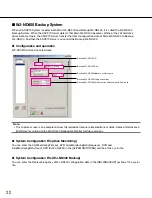
Страница 33: ...ine or all hard disk drives of Main WJ ND400 become failure For more details please refer to the WJ ND400 Backup Operation Monitor software Help file 1 Connect the Main WJ ND400 and Backup WJ ND400 to the same network 2 Add the information of Main WJ ND400 and Backup WJ ND400 to Admin Console s both Components Digital Recorders Records screen and Components Digital Recorders Backup Records screen ...

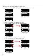
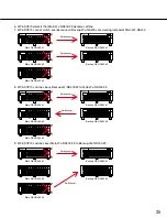
Страница 34: ... 1 to Backup WJ ND400 1 4 WV ASC970 detects that Main WJ ND400 2 becomes offline 5 WV ASC970 switches over Main WJ ND400 2 to Backup WJ ND400 2 Main WJ ND400 1 Backup WJ ND400 1 Main WJ ND400 2 Backup WJ ND400 2 Main WJ ND400 3 Main WJ ND400 1 Switchover Backup WJ ND400 1 Main WJ ND400 2 Backup WJ ND400 2 Main WJ ND400 3 Main WJ ND400 1 Switchover Backup WJ ND400 1 Main WJ ND400 2 Backup WJ ND400 ...

Страница 35: ...2 to Main WJ ND400 2 9 WV ASC970 switches over Main WJ ND400 3 to Backup WJ ND400 2 Main WJ ND400 1 Switchover Backup WJ ND400 1 Main WJ ND400 2 Backup WJ ND400 2 Main WJ ND400 3 Switchover Main WJ ND400 1 Switchover Backup WJ ND400 1 Main WJ ND400 2 Backup WJ ND400 2 Main WJ ND400 3 Switchover Main WJ ND400 1 Switchover Backup WJ ND400 1 Main WJ ND400 2 Backup WJ ND400 2 Main WJ ND400 3 Switchove...

Страница 36: ... switchover recording is skipped Once a Main WJ ND400 is switched over even if the dedicated Backup WJ ND400 becomes failure WV ASC970 Server doesn t switch over the Main WJ ND400 to other Backup WJ ND400 If another user is currently configuring the settings of WJ ND400 WV ASC970 Sever can t switch over It is necessary that firmware version of Main WJ ND400 and Backup WJ ND400 are same Alarm notif...

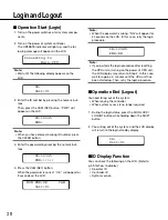
Страница 37: ...e following circum stances When you have entered a wrong user ID or pass word etc When you have entered a camera number or moni tor number etc that is not existing Busy When a selected monitor is controlled by a higher level user blinks on the LCD You cannot con trol the monitor When a selected camera is controlled by a higher level user blinks on the LCD You cannot con trol the camera To cancel t...

Страница 38: ...345 PWD MON PWD OK CAM Unit 01 Note When the password is wrong NG will appear for 2 seconds on the LCD In this case retry the login procedure Note If you perform the login procedure after resetting the CPU unit or turning on the power of CPU unit the LCD display may return to Step 2 In this case wait for approx 5 minutes until the CPU unit has been started up Then retry the login procedure Operati...

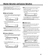
Страница 39: ...Selection Note To select the next or previous camera number press the or button In case of global camera numbering method the LCD shows a camera number up to 7 digits as shown below In case of global camera numbering method when a local operator press or button the foreign domain s camera will be skipped Monitor Lock Monitor lock is the function to retain other operators control of a monitor even ...

Страница 40: ...y Setting for Controller Adjustment of LCD Display and Buzzer You can perform the settings of LCD brightness LCD contrast alarm buzzer or button buzzer Refer to WV CU950 Operating Instructions for how to adjust ...

Страница 41: ...WIDE 4 Press the IRIS OPEN or CLOSE buttons to open close the lens iris The lens iris is adjusted by these buttons to obtain the proper image exposure Note To return the lens iris to the factory default status press the A button of 3D joystick unit Pan Tilt Control Manual Operation 1 Select the desired monitor and camera Refer to p 39 Monitor Selection and Camera Selection 2 Move the 3D joystick t...

Страница 42: ...ected a wrong number press the CLEAR button to clear the numeric input 3 Press the PRESET PGM PRESET button The camera will move to the preset position and the image of selected preset position will be displayed on the active monitor Note To call preset positions you must set preset posi tion numbers for the camera in advance Wiper Control The following procedure is available when a selected camer...

Страница 43: ...xiliary control devices The following procedure is available when an auxiliary control device such as Receiver WV RC150 is con nected to a system unit Operating Procedure 1 Select the desired monitor and camera Refer to p 39 Monitor Selection and Camera Selection 2 Press the AUX 1 ON OFF or AUX 2 ON OFF but ton The auxiliary control device associated by the installation wiring will be activated 3 ...

Страница 44: ...Selection and Camera Selection 2 Enter the desired camera function number by pressing the numeric buttons Note When you select a wrong number press the CLEAR button to clear the numeric input 3 Press the CAM FUNC SYS FUNC button CamF nnn will appear on the LCD Note Refer to Operating Instructions of camera for details on available shortcuts Other Camera Functions The following functions are availa...

Страница 45: ...number MON 1 CAM 0123 Unit 01 00512 MON A001T0001R CAM 0123 Unit 01 00512 MON A001T0001P CAM 0123 Unit 01 00512 Note To switch to the next sequence step press the button during sequence pause To switch to the previous sequence step press the button during sequence pause To resume the sequence press the TOUR SEQ GROUP SEQ again 5 To return to spot monitoring press the SEQ PAUSE SEQ STOP button whil...

Страница 46: ...ence number area on the active moni tor Note To switch to the next sequence step press the button during sequence pause To switch to the previous sequence step press the button during sequence pause 4 To return to spot monitoring select one of the monitors that are being run on the selected group sequence Then press the SEQ PAUSE SEQ STOP button while holding down the SHIFT but ton Note You can al...

Страница 47: ...MON OSDAll Off CAM 0123 Unit 01 00512 07 07 1999 03 37 21 PM M a1 ALM T R A C CAMERA TITLE Clock General status Monitor status Camera ID Axx alarm number 0 to 9 alarm action number alarms behind Playback on WJ GXD400 Pause on WJ GXD400 2 3 4 5 6 7 FWD on WJ GXD400 2 3 4 5 6 7 REW on WJ GXD400 Record end Note Every time you press the OSD button the OSD items will be displayed or hidden When the OSD...

Страница 48: ... Note Only WJ SX650 or WJ SX850 switch node Video Loss History Table Refer to p 58 Video Loss History Table Note Only WJ SX650 or WJ SX850 switch node Multi Screen Segment Control The CU950 can switch three type of multi screen seg ment for WJ GXD400 1 Select the desired monitor 2 Enter the desired segment number 1 3 left large or 6 Note WV ASC970 does not support the right large multi screen 3 Pr...

Страница 49: ...press the but ton To select the previous alarm number press the button MON 1 CAM 0123 Unit 01 00512 MON Alarm00001 CAM 0123 Armed 00512 Alarm Arming Control 1 Select a desired alarm Refer to Alarm Selection 2 Every time you press the ALARM ALM SUSPEND button the selected alarm will be armed or dis armed When an alarm is disarmed the LCD dis play will become as follows 3 To exit the alarm mode pres...

Страница 50: ...K status will be can celed cancelled Then enter the alarm action number by pressing the numeric buttons and press the ACK button again MON 9 CAM 0123 Active 00512 MON Alarm00001 CAM 0123 Ack 9 00512 To Cancel Alarms 1 Perform Step 1 to 2 of p 49 Alarm Selection 2 Press the ALM RESET ALM ALL RESET button to reset the alarm Reset will be displayed on the LCD Note To reset all the alarms at a time pr...

Страница 51: ... not set in the admin console DATE TIME Date and time when alarm state changes 3 To display the next page press the button To display the previous page press the button MON AlarmHist CAM 0123 00512 ALARM HISTORY PG ALM STATE DATE TIME 1 DISARMED 01 01 01 12 00 1 ARMED 01 01 01 12 00 1 ACTIVE 01 01 01 12 00 1 ACKED 01 01 01 12 00 1 CLEARED 01 01 01 12 00 1 RESET 01 01 01 12 00 Note To display the f...

Страница 52: ... select a cam era while live images are being displayed on the monitor MON DVR 0123 Unit 01 00512 MON DVR 0123 Unit 01 00512 Note WV ASC970 does not support the manual selec tion feature for network disk recorder Time Date Search Playback You can search playback images by entering a desired recording date and time Note To cancel the entry press the MON ESC or EXIT button The LCD display will retur...

Страница 53: ...appear on the LCD 2 Press the MENU button repeatedly until a desired menu appears Refer to pages 54 to 59 Note When you press the MENU button repeatedly while holding down the SHIFT button each menu will appear in the reverse order You can also select the menu by rotating the JogDial clockwise or counterclockwise 3 Perform the operations to activate the selected function The operating procedure di...

Страница 54: ...the 3D joystick Then press this button Note Depending on the camera model CAMERA RESET is not displayed on the camera setup menu In this case the F4 button is unavailable This function is available in only for WJ SX650 or WJ SX850 CamMenu 001 On 5Off Rst A Rst Auto Mode 1 Select a desired monitor and camera Refer to p 39 Monitor Selection and Camera Selection 2 Display Auto Mod menu Refer to Step ...

Страница 55: ...r the patrol learn setup will automatically stop 5 To quit the patrol learn setup press the F2 Stop button Patrol 004 Start Stop Group Preset Note This function is available only when Group Preset setting has been established through the admin console Refer to the Admin Console User s Guide A Group Preset determines which monitor is to be assigned to which camera Therefore monitor selec tion is no...

Страница 56: ...r to Step 1 and 2 of p 53 To Recall Menu Functions DigiOut 007 Set AlmStat 008 On Off Blk 3 Select a desired function by pressing one of the F1 to F3 buttons Available buttons and functions F1 On Opens the ALARM STATUS table F2 Off Closes the ALARM STATUS table F3 Blk Changes the monitor background between camera images and black picture NAME Alarm text Refer to p 51 for other columns on the table...

Страница 57: ...34567890 6400 999 SX ABV OUT 1234567890 6400 999 SX BLW IN 1234567890 6400 999 SX BLW OUT 1234567890 Note To display the first page of table press the but ton while holding down the SHIFT button To display the last page of table press the button while holding down the SHIFT button 5 To exit the VIDEO LOSS table perform either of the following Select a camera Refer to p 39 Camera Selection Press F2...

Страница 58: ... just up to 7 digits number And also the tour sequence number is up to 4 digits number i e C1234567 Camera 1234567 T501P Tour Sequence 501 Puase While the WV ASM970 performs the synchronous playback the CAM DVR SEQ field displays previ ous status for dedicated monitors 5 To exit the SYSTEM STATUS table perform either of the following Select a camera Refer to p 39 Camera Selection Press the MON ESC...

Страница 59: ...e assignments of monitor surveillance areas has been established through admin console Refer to the Admin Console User s Guide 1 Display Area No menu Refer to Step 1 and 2 of p 53 To Recall Menu Functions Area No 1 012 Set 2 Select an area number by pressing the numeric buttons Note If you have selected an area not assigned through the admin console operations will become unavailable In this case ...

Страница 60: ...WJ SX650 32 Coaxial Cables 32 Coaxial Cables WJ PB65E01 WJ PB65E01 WJ PB65E01 Not used Not used Video Input Board 2 Video Input Board 1 Video Output Board 2 Video Output Board 1 Not used Not used Video Input Board 8 Video Input Board 7 Video Input Board 6 Video Input Board 5 Video Input Board 4 Video Input Board 3 Video Input Board 2 Video Input Board 1 Video Output Board 2 Video Output Board 1 No...

Страница 61: ... hub units This system can support up to six WJ SX650 SubNodes The Server assigns the IP address to each SubNode based on the admin console database Switching HUB SX650 SubNode 1 SX650 SubNode 3 SX650 SubNode 6 SX650 SubNode 2 SX650 SubNode 4 SX650 SubNode 5 192 168 200 4 192 168 200 6 192 168 200 3 192 168 200 5 192 168 200 1 192 168 200 2 192 168 200 200 Sever PC WV ASC970 This illustration show...

Страница 62: ...r ON ON ON ON OFF OFF OFF OFF Operation Mode Main CPU Mode Address Address 1 ON ON ON ON OFF OFF OFF ON Main CPU Mode Address 2 ON ON ON ON OFF OFF ON OFF Main CPU Mode Address 3 ON ON ON ON OFF OFF ON ON Main CPU Mode Address 4 ON ON ON ON OFF ON OFF OFF Main CPU Mode Address 5 ON ON ON ON OFF ON OFF ON Main CPU Mode ON ON ON ON OFF ON ON OFF Address 6 Main CPU Mode Address 7 ON ON ON ON OFF ON O...

Страница 63: ...t Board 2 Camera Input Connecters 17 Input Board 1 Monitor Output Connectors 16 Output Board 2 Camera Input Connecters 32 Input Board 1 1 2 Video Connection between SubNode 2 and SubNode 3 Bridge SubNode 2 SubNode 3 Monitor Output Connectors 1 Output Board 1 Camera Input Connecters 1 Input Board 2 Monitor Output Connectors 16 Output Board 1 Camera Input Connecters 16 Input Board 2 Monitor Output C...

Страница 64: ...nput Connecters 32 Input Board 1 1 4 Video Connection between SubNode 5 and SubNode 6 Bridge SubNode 5 SubNode 6 Monitor Output Connectors 1 Output Board 1 Camera Input Connecters 1 Input Board 2 Monitor Output Connectors 16 Output Board 1 Camera Input Connecters 16 Input Board 2 Monitor Output Connectors 1 Output Board 2 Camera Input Connecters 17 Input Board 2 Monitor Output Connectors 16 Output...

Страница 65: ... OUT 3 Input Board 4 Camera Input Connecters 17 to 24 Input Board 4 VIDEO OUT 4 Input Board 4 Camera Input Connecters 25 to 32 Input Board 4 VIDEO OUT 1 Input Board 5 Camera Input Connecters 1 to 8 Input Board 5 VIDEO OUT 2 Input Board 5 Camera Input Connecters 9 to 16 Input Board 5 VIDEO OUT 3 Input Board 5 Camera Input Connecters 17 to 24 Input Board 5 VIDEO OUT 4 Input Board 5 Camera Input Conn...

Страница 66: ...cters 17 to 24 Input Board 4 VIDEO OUT 4 Input Board 4 Camera Input Connecters 25 to 32 Input Board 4 VIDEO OUT 1 Input Board 5 Camera Input Connecters 1 to 8 Input Board 5 VIDEO OUT 2 Input Board 5 Camera Input Connecters 9 to 16 Input Board 5 VIDEO OUT 3 Input Board 5 Camera Input Connecters 17 to 24 Input Board 5 VIDEO OUT 4 Input Board 5 Camera Input Connecters 25 to 32 Input Board 5 VIDEO OUT...

Страница 67: ...e number used here is the number of the Ethernet ports on WV ASC970 Server Interface Definitions Interface Number IPA SUBNET MASK BOOT SERVER IPA Note The InterfaceX IPAs must match the MainX CPU hardware settings in order for the System to operate correctly MainA CPU In Standard System the WV ASC970 Server should use the IP addresses that follow In this case the MainB CPU s interface numbers shou...

Страница 68: ...SC970 Server has 3 software processes listed above to communicate to a CU950 All processes should use same interface number Factory default setup is interface 1 Set Swcpu to the same interface_num for all unit CPUs Swcpu 0 0 means interface0 in INTERFACES section In case of Redundant System Both CPUA and CPUB must be assigned the same interface_num Factory default setup is interface 0 Set UnitMana...

Страница 69: ...format 5 DD MM YY format 6 MM DD YY format 7 DD Mmm YY format 8 YY MM DD format 9 Mmm DD YY TimeDateFormat 1 Time Hour Display format Format TimeHourFormat format format 0 12 Hour format 1 24 Hour TimeHourFormat 0 UNIT section Note The unit ID should be unique number from 1 to 64 in the multiple domain system In case of single domain sys tem this number should be 1 UNIT The unit ID should be the s...

Страница 70: ...l alarm port only Other use of the port such as for an external controller must be configured using the admin console RS232ALARM This section is optional It is not required unless System defaults are not acceptable Delete the single asterisks below to make this section active Enable Disable Serial Alarms by port Format AlarmPort port 1 port 2 port 3 port use 1 to indicate desired port only one por...

Страница 71: ...tain network parameters If changes are necessary consult your network administrator ROUTING This section is optional to the system It is only required for external gateway Delete the single asterisks to make this section active Only one default gateway is allowed Format default gateway IPA The factory default settings below are up is commented out by default 192 168 200 1 Network entries must be g...

Страница 72: ...on allow user to change some settings for the ASM970 Client Software Time Line feature TIMELINE This section allow user to change polling frequency of retrieving the DVR and alarm information for the ASM970 Client Software Time Line feature Format TimeLine Minutes Days Model Minutes Frequency to retrieve from DVR 5 30 min Days days to save on HD 1 9999 Mode 0 off 1 on default TimeLine 10 7 1 This ...

Страница 73: ...y Format AliveMonitoringRetryCount_DVR Retry Count Timeout Time out of monitoring for DVR 1 60 sec Retry Frequency Retry frequency of monitoring for DVR 1 60 sec Retry Count Retry Count of monitoring for DVR 1 10 AliveMonitoringTimeout_DVR 12 AliveMonitoringRetryFrequency_DVR 3 AliveMonitoringRetryCount_DVR 3 This section allow user to change timeout retry frequency and retry count of alive monito...

Страница 74: ...rieve frequency of configuration data from WJ ND400 60 3600 sec RetrieveFrequency 60 This section allow user to change the setting of deleting switchover history Format DeleteHistoryOnBoot Delete flag Delete flag Delete switch over history when WV ASC970 is reset 0 or 1 0 not delete 1 delete DeleteHistoryOnBoot 0 DNS section This section allow user to change the setting of DNS server DNS This sect...

Страница 75: ... cannot display the same video stream from WJ HD616 WJ HD716 on more than two monitors of same WJ GXD400 or WV ASM970 L3SW 1 172 16 192 1 WJ HD616 716 Cam1 Cam2 Cam3 Cam4 Cam5 Cam6 Cam7 Cam8 172 16 192 20 172 16 192 60 WJ GXD400 WV LW2200 WV CU950 PC with Admin Console 172 18 0 9 System Controller Ethernet 172 18 0 10 L3SW 2 PC with Client software WV ASM970 172 18 0 11 172 18 0 1 Sever PC WV ASC9...

Страница 76: ...ration DVR Line Speed HTTP PORT DHCP IP Address Gateway Schedule Authentication ID Passwd 1 AUTO 0080 OFF 172 16 192 60 16 0 0 0 0 Always Recording Default Note The WJ HD616 or WJ HD716 series should be set the alarm suspend configuration L3SW 1 Setup Set a restriction for the multicast packets not to flow to Server PC port Valid the IGMP V2 due to support Multicast packets L3SW 2 Setup Set a rest...

Страница 77: ...perator fails to login Check whether global database has been updated for this operator Users typed correct password WV ASC970 Admin Console User s Guide Global Operator fails to select a global camera Check whether the global operator subjects to the camera unit partitioning Check whether you enter a correct unit id for the global camera P 27 P 8 Global Operator fails to start a global tour seque...

Страница 78: ...le cause Possible solution Reference page The WV ASC970 does not work as expected when the system administrator updates the Admin data base Check whether the updated items belong to the global database If yes put the global database and reboot the WV ASC970 WV ASC970 Admin Console User s Guide DVR Disk Configuration Menu Related problems Symptom Possible cause Possible solution Reference page The ...

Страница 79: ...ew Jersey 07094 U S A Panasonic Canada Inc 5770 Ambler Drive Mississauga Ontario L4W 2T3 Canada 905 624 5010 www panasonic ca Panasonic System Networks Co Ltd 2010 N1009 6032 3TR006365GAB Printed in Japan For Europe and other countries Panasonic Corporation http panasonic net Importer s name and address to follow EU rules Panasonic Testing Centre Panasonic Marketing Europe GmbH Winsbergring 15 225...

Отзывы: