background image

374

DP-2330/3030

MAR 2005

Ver.2.1

DP-2310/3010

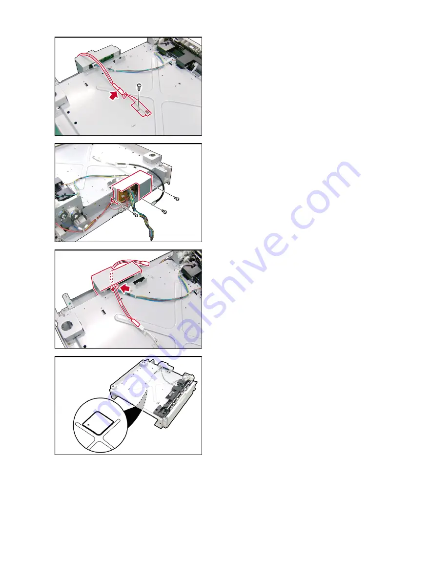
(16) Install the 

Heater

 Assembly.

(17) Secure the 

Heater

 Assembly with 1 Screw.

(18) Connect the 

Heater

 Assembly to the HT5 

Harness.

(19) Install the 

Harness Clamp

.

(20) Insert the 

HT5 Harness

 to the Harness Clamp.

(21) Remove 3 

Screws

.

(22) Remove the 

Protection Plate

.

(23) Route the 

HT5 Harness

 and secure to the 

Harness Clamp.

(24) Reinstall the 

Protection Plate

.

(25) Pull the 

2nd Paper Tray

 out.

(26) Install the 

Protection Sheet

.

Содержание Workio DP-3030

Страница 1: ...se non technical individuals of potential dangers in attempting to service a product Products powered by electricity should be serviced or repaired only by experienced professional technicians Any att...

Страница 2: ...PCB Caution Pb free solder has a higher melting point than standard solder typically the melting point is 50 70 F 30 40 C higher Please use a soldering iron with temperature control and adjust it to 7...

Страница 3: ...e Hard Disk Drive Unit is installed to prevent a Disk Scan Function from being performed similar to Windows OS when the power is abruptly interrupted it is important to follow the step sequence below...

Страница 4: ...4 Beispiel DP 2330 3030 Hinweis...

Страница 5: ...a live connector can cause arcing consequently deforming the plug and cause fire When disconnecting the machine grasp the plug instead of the cord Pulling on a cord forcibly can damage it and cause fi...

Страница 6: ...iguration or modify any parts An unauthorized modification can cause smoke or fire Consumable Safeguards Never dispose of toner toner cartridge or a waste toner container into an open flame Toner rema...

Страница 7: ...aper that is difficult or impossible to see do not try to remove it by yourself Doing so can cause injuries or burns Switch Off the machine immediately and wait until it cools down Consumable Safeguar...

Страница 8: ...8 memo...

Страница 9: ...ervice Modes For Facsimile 203 System Description 233 6 1 Printing Process 233 6 2 Precaution with Consumables 234 6 3 New Image Stabilizing Technology 236 6 4 Mechanical Operation 239 6 5 Automatic D...

Страница 10: ...eeder DA AR251 for DP 2330 3030 354 8 29 Installing the Platen Cover DA UC200 360 8 30 Installing the Key Counter Harness Kit DA KH200 361 8 31 Installing the Dehumidifier Heater Kit DZTQ000048 363 8...

Страница 11: ...S For EU FLS 8 x 13 in 8 5 x 13 in A3 B4 A4 A4 R B5 B5 R For Other Destinations Bypass LDR LGL LTR LTR R INV R For USA and Canada A3 A4 A4 R A5 A5 R B4 FLS For EU FLS 8 x 13 in 8 5 x 13 in A3 B4 A4 A4...

Страница 12: ...16 MB 23 Standard Page Memory Size 32 MB 24 Exit Tray Capacity Standard 250 sheets 25 Color No 26 Dimensions W x D x H 23 58 x 27 83 x 27 44 in 599 x 707 x 697 mm H To Platen Glass 27 Operating Space...

Страница 13: ...Free Stop Yes From 30 to 70 degrees 5 Inverting ADF i ADF Duplex Type Standard For USA and Canada Option For EU and Other Destinations Original Set Face Up Scanning Method Sheet Through Capacity Origi...

Страница 14: ...with Finisher Tray Position Outer Number of Bins 1 Face Up Face Down Face Down Bin Capacity 250 sheets LTR A4 Multi Tray Function Yes Max 3 way using Optional Exit Trays Inner and Outer Shift Tray Fu...

Страница 15: ...by the General Functions setting Standby Mode Yes 140Wh Energy Saver Mode Yes 28W Sleep Mode Yes 18W Turns Off the Heater Power Shutdown Mode Yes 3W 100 VAC Power Supply Network Function not availabl...

Страница 16: ...2 2 Yes Book 2 Yes 1st Page BLANK Yes 1 2 2 1 2 2 1st Page IMAGE Yes Book 2 Image Rotation 90 or 270 Yes Electronic Sorting Yes Rotation Sorting Yes Insertion Job Cover Mode Yes Available when using t...

Страница 17: ...ion Mode Yes Original Detection Release No Interrupt Yes Reset Yes One Touch key No Mode Change Yes Copier Printer NW Scanner Fax and Internet Fax Mode LCD Main Indication Message Language Default Eng...

Страница 18: ...Platen Glass 11 02 lb 5 kg ADF with Document Guide Yes Clip Pocket Yes Operating Instructions Pocket No Warning Caution Label Specified Language 5 Optical System Original Detection Method Reflective P...

Страница 19: ...r No Toner Waste Container No Outer Tray No Option Operating Instructions Yes Power Supply 1 Power Requirement 99 138 VAC 47 63 Hz Single phase 100 VAC Power Supply 180 264 VAC 47 63 Hz Single phase 2...

Страница 20: ...3 85 Fine 203 x 196 8 x 7 7 S Fine 203 x 391 8 x 15 4 406 x 391 16 x 15 4 600dpi 600 x 600 dpi 600 dpi communication is only available between WORKiO DP 2310 3010 3510 4510 6010 and other T 30 compli...

Страница 21: ...1 150 sheets Optional max 2250 sheets 7 Collation Stack Yes Face Down 8 Consumable Toner Bottle Developer OPC Drum and Staples Fax Memory 1 Standard Memory DP 2330 3030 3 MB 180 pages DP 2310 3010 2 M...

Страница 22: ...ons 5 Direct Deferred Transmission No ADF Deferred Transmission 6 Deferred Transmission Yes Max 50 timers 7 Deferred Multi Station Transmission Yes 8 Priority Direct Transmission Yes Priority ADF Tran...

Страница 23: ...h Panel Display 2 Voice Contact No 3 Edit File Mode Yes With View Mode 4 Incomplete File Save Yes With View Mode 5 Automatic Cover Sheet Yes Certainty 1 Verification Stamp Yes 2 Header Total Page Prin...

Страница 24: ...r Only with Internet FAX Option 11 Sub Address XMT Yes T Routing 12 Sub address RCV No 13 OMR XMT No Standards 1 PSTN FCC Part 68 1997 Industry Canada No CS 03 Issue 8 1996 Others 1 Fax Access Code Ye...

Страница 25: ...USB Ethernet 6 OS Win 98 Win Me Win NT 4 0 Win 2000 Win XP MAC 8 6 10 1 MAC 8 6 10 1 is PS only 7 GDI Yes 8 PDL PCL6 Yes Requires Optional PCL6 Emulation Kit 9 PDL PS3 Yes Requires Optional PS PCL6 Em...

Страница 26: ...Image No 1 A4 Std Resolution JBIG 600 dpi Excluding Data XMT Time 3 Halftone 256 Halftone Shades With Error Diffusion 4 Max Document Size Ledger A3 5 Scanning Resolution dpi 600 x 600 300 x 300 150 x...

Страница 27: ...3 85 Fine 203 x 196 8 x 7 7 S Fine 203 x 391 8 x 15 4 406 x 391 16 x 15 4 600dpi 600 x 600 dpi LAN 600 dpi 16 x 15 4 Scanning Resolution is available with Parameter setting Printer Mechanism 1 Printi...

Страница 28: ...es Using Sub Address Local print available Phone Book Registration from PC Yes Via Email 4 Internet Fax Parameters Registration via Email Yes 5 Internet Delivery Confirmation Yes With MDN 6 Network Sc...

Страница 29: ...er Tray CST3 PC Board 4th Paper Tray CST2 PC Board 1 Bin Finisher or Exit Tray Outer Motor Sensor SL Solenoid Sensor Dehumidifier Heater Kit Option Standard Configuration Panel PNL PC Board Key Counte...

Страница 30: ...B Expansion Flash Memory Card 4 MB UE 410047 Additional Memory for Fax Internet Fax Expansion Flash Memory Card 8MB UE 410048 Image Memory 16MB DA SM16B For Electronic Sorting Image Memory 64 MB DA SM...

Страница 31: ...Page Description Language of the Hewlett Packard Company PS3 is a Page Description Language of the Adobe Systems Company Available in Specified Destinations Part Name Part Number Remarks Toner DQ TU1...

Страница 32: ...S Rules 21 CFR Subchapter J in effect at date of manufacture For USA Only Front View Right View Left View Top View Rear View CAUTION THIS PRODUCT CONTAINS A LITHIUM BATTERY DANGER OF EXPLOSION IF BATT...

Страница 33: ...00 mm 3 94 in 100 mm 10 83 in 275 mm 14 84 in 377 mm 9 88 in 251 mm 3 46 in 88 mm 3 94 in 100 mm 3 94 in 100 mm 3 94 in 100 mm 3 94 in 100 mm 3 94 in 100 mm 3 94 in 100 mm 3 94 in 100 mm 3 94 in 100 m...

Страница 34: ...rs I and O For Example DP 2310 PU DP 3010 PU Production Facility Production Year Starting with Year 2001 the last 2 digits of the year is represented as A T A 01 2001 K 11 2011 B 02 L 12 C 03 M 13 D 0...

Страница 35: ...35 DP 2330 3030 MAR 2005 Ver 2 1 DP 2310 3010 1 6 Control Panel DP 2310 3010 DP 2330 3030...

Страница 36: ...otor 1801 Transport Motor 1320 Toner Motor 958 Lift DC Motor 1152 Fan 459 ILS PCB 19124 Front Cover Sensor Paper Feed Roller Clutch 1105 Paper Feed Roller Clutch 1105 Intermediate Roller Clutch 957 Sh...

Страница 37: ...Optional LVPS 1912 NFL PCB 1909 RLB PCB 1917 ACD PCB 1904 ADF PCB 1907 PNL3 PCB 113 EXFD PCB 1978 MJR PCB 1915 DC PCB 1905 FXB PCB 1916 SDR PCB 1903 PNL2 PCB 123 CDS PCB 1986 WTS PCB 1982 SC PCB 1901...

Страница 38: ...38 DP 2330 3030 MAR 2005 Ver 2 1 DP 2310 3010 2 Disassembly Instructions 2 1 General Disassembly Pertinent Disassembly Instruction sections are shown below...

Страница 39: ...t Tray 1604 4 Slightly pull the right edge of the ADF Rear Cover upward 5 Release the Latch Hooks 6 Remove the ADF Rear Cover 1601 7 Lower the ADF Input Tray back in place 8 Disconnect the AMT Harness...

Страница 40: ...7 Note Release 3 Latch Hooks in alphabetical order and in the direction as shown by each arrow 24 Remove 4 Screws 19 25 Remove the Upper ADF Guide 1723 26 Remove the Snap Ring S9 27 Remove the Torque...

Страница 41: ...34 Remove the ADF Motor 1801 35 Remove 6 Screws 19 36 Remove the Sensor Bracket 1663 37 Remove 4 Screws 19 38 Remove the Motor Bracket 1811 and Gear Bracket 1802 Assemblies Note Apply Molykote EM 50L...

Страница 42: ...Roller 1728 Pre Feed Roller 1731 Drive Roller 1872 and the Feed 2 Roller 1753 with a soft cloth saturated with isopropyl alcohol Cleaning Exit Roller and Inverting Feed Roller 3 Lift the ADF Input Tr...

Страница 43: ...lver Screws B1 4 Remove the Left Platen Cover 514 and the Right Platen Cover 516 5 Remove 2 Silver Screws B1 6 Slightly lift the Control Panel Assembly 7 Disconnect 4 Harnesses on the PNL1 PC Board CN...

Страница 44: ...n the PNL2 PC Board CN251 15 Remove the PNL2 PC Board 123 Note After reassembling the Control PNL2 PC Board make sure that the Battery Holder is reinstalled 16 Disconnect the Harness on the INV PC Boa...

Страница 45: ...2 1 DP 2310 3010 21 Remove 1 Screw P5 22 Remove the PNL4 PC Board 114 23 Remove 4 Screws P5 24 Remove the PNL3 PC Board 113 25 Remove 2 Screws H4 26 Remove 2 Screws H4 27 Remove the LCD Module 128 28...

Страница 46: ...and the Control Panel Assembly Refer to 2 2 2 2 Remove 2 Screws 19 3 Remove the Glass Assembly 557 4 Remove the Glass S 559 5 Holding by the center slowly move the Lamp Base Assembly to the center of...

Страница 47: ...0 13 Remove Mirror 1 264 Note Observe the position of the Mirror 1 before removing it The Black Mark on the Mirror indicates non reflective side When reinstalling make sure the smooth side of Mirror 1...

Страница 48: ...rame 22 Disconnect the Harness on the LFB PC Board CN181 23 Remove 1 Screw 19 24 Remove the FPC Cable Holder B 216 Assembly 25 Remove 2 Sliders on the Connectors 26 Remove the FPC Cable 260 Note The S...

Страница 49: ...move the MXL34 Pulley 217 34 Remove 1 Screw 6P 35 Remove the Fan 459 36 Disconnect the Harness on the Scanning Motor 37 Remove 3 Screws 19 38 Remove the Motor Bracket 249 Assembly Note When reinstalli...

Страница 50: ...nd remove the Ferrite Core 43 Remove 3 Red Screws D24 44 Remove the CCD Assembly 207 Note When reinstalling the CCD Assembly align the hole with the Red Mark on the CCD Assembly with the hole on the S...

Страница 51: ...48 Remove the SDR PC Board 1903 49 Remove 6 Screws 19 50 Remove the F R Scanner Frame 240 51 Remove 2 Red Screws D24 52 Remove the Rear Lamp Belt Lock 228 53 Remove the Front Lamp Belt Lock 227 54 Re...

Страница 52: ...racket 233 Assembly 60 Remove the 4 Mirror 2 Plate Springs 206 61 Remove the two Mirror 2 265 62 Remove the 3 Sliders 211 Reinstalling the Lamp Base Assembly and the Mirror 2 Bracket Assembly 1 Remove...

Страница 53: ...secure the Rear Mirror Belt Lock 238 and the Front Mirror Belt Lock 236 with 2 Screws 18 6 Install the Lamp Base Bracket 224 Assembly Note The Bracket must be adjusted by moving it towards the right...

Страница 54: ...54 DP 2330 3030 MAR 2005 Ver 2 1 DP 2310 3010 8 Clean the Mirror 1 264 and both the Mirror 2 265 with a soft cloth saturated with isopropyl alcohol...

Страница 55: ...e the Harness Cover 1525 4 Unlock the Angled Rear Arm 1218 and the Front Arm 1217 5 Open the Right Cover and hook the Angled Rear Arm into the lower Hook Hole 6 Open the Front Cover 528 7 Remove the T...

Страница 56: ...t with bare hands Caution The OPC Drum is sensitive to light To prevent optical exposure problems do not expose the OPC Drum to direct sunlight or bright light even if it is a 1000 Lux fluorescent lam...

Страница 57: ...e Hopper Unit insert the hooks into the recessed holes on the Developer Unit as illustrated 22 Release 3 Latch Hooks and remove the Developer Cover 825 Removing the Old Developer and Toner 23 Stand th...

Страница 58: ...ller Sheets are outside as illustrated Removing the Old OPC Drum 29 Remove the OPC Drum Shaft Holder Assembly 30 Lift the OPC Drum holding the right side where the OPC Drum Shaft Holder Assembly was i...

Страница 59: ...728 Assemblies Note When reinstalling the Bias Charge Roller Holder Assembly on the rear side install the Bias Charge Roller Holder 728 first and then the Bias Charge Roller Bushing 726 with the Bushi...

Страница 60: ...the Right Cover 1201 2 Remove 1 Screw 6P 3 Remove the Harness Cover 1525 4 Unlock the Angled Rear Arm 1218 and the Front Arm 1217 5 Remove 1 Screw 6P 6 Remove the Support Plate 476 7 Remove 1 Screw 6P...

Страница 61: ...es 11 Remove 4 Screws 4N 12 Remove the Fuser Unit 13 Remove 4 Screws 6P 14 Remove the Dual Path Exit Guide 15 Clean the Feed Roller 1510 with a soft cloth saturated with isopropyl alcohol 16 Clean the...

Страница 62: ...1 20 Disconnect the Harness 21 Remove the Cleaning Web Roller Unit 22 Remove 1 Screw 21 23 Remove the Rear Web Bracket 1071 24 Remove the Cleaning Web Roller 1083 and Web Pressure Roller 1080 25 Remov...

Страница 63: ...1 DP 2310 3010 31 Remove 3 Screws 23 32 Remove 2 Screws 19 33 Remove the Harness Guide 1004 34 Remove 1 Screw 21 35 Remove the Rear Lamp Holder 1021 36 Remove 2 Screws 16 37 Remove 1 Screw 21 38 Remo...

Страница 64: ...ke sure that the 600W Fuser Lamp White Harness is plugged into the upper left slot and the 450W Fuser Lamp Red Harness is plugged into the lower right slot 4 Route the Harnesses White Black and Red al...

Страница 65: ...046 Note 1 The Plate Spacer is installed only to the non Gear side 2 Do not scratch the surface of the Fuser Roller when removing or reinstalling it Cleaning Insulation Bushings Clean the Insulation B...

Страница 66: ...030 MAR 2005 Ver 2 1 DP 2310 3010 51 Remove the Exit Roller 1028 52 Remove the Turn Guide 1007 53 Remove 1 Screw 19 54 Remove the Upper Guide 1001 55 Remove 5 Upper Fingers 1067 56 Remove the Pressure...

Страница 67: ...nstalling make sure to install with Bearing s Retainer Ring facing towards the Roller 2 Do not scratch the surface of the Pressure Roller when removing or reinstalling it Cleaning Pressure Roller Clea...

Страница 68: ...Rear Cover 302 3 Remove 4 Silver Screws S6 4 Remove the Rear Right Cover 507 and the Right Rear Cover 518 5 Remove 2 Silver Screws B1 6 Remove the Lower Rear Cover 506 7 Remove 1 Screw 24 8 Remove 5...

Страница 69: ...rews 4N 14 Remove the Main Motor 907 15 Disconnect the Connector on each of the 3 Clutches 16 Remove 3 Snap Rings S9 17 Remove 3 Clutches 969 1105 x 2 18 Release The Harnesses from 4 Harness Clamps 19...

Страница 70: ...70 DP 2330 3030 MAR 2005 Ver 2 1 DP 2310 3010 23 Remove 3 Screws 19 24 Remove the Motor Bracket 908...

Страница 71: ...o the lower hook hole Cleaning the CDS PC Board Clean the Sensor on the CDS PC Board with a dry soft cloth 6 Remove the Lower Rear Cover 506 Refer to 2 2 6 7 Disconnect 3 Connectors 8 Release the Harn...

Страница 72: ...g Registration Pinch Roller Clean the surface of the Registration Pinch Roller with a soft cloth saturated with isopropyl alcohol 13 Remove the Roller Cleaner 1229 Note When installing the Roller Clea...

Страница 73: ...30 3030 MAR 2005 Ver 2 1 DP 2310 3010 16 Remove the BTR Gear 1234 17 Remove the Bias Transfer Roller 1221 Cleaning Bias Transfer Roller Clean the surface of the Bias Transfer Roller only with a soft d...

Страница 74: ...Guide 1203 6 Remove 1 Screw 19 7 Remove the Feed Roller 1244 Cleaning Feed Roller Clean the surface of the Feed Roller with a soft cloth saturated with isopropyl alcohol For DP 2310 3010 8 Remove the...

Страница 75: ...Roller Guide 1294 12 Remove the Reverse Roller 1291 Assembly 13 Remove the Bushing 1286 14 Remove the Washer 1288 15 Remove the E Ring J7 16 Remove the Reverse Roller 1291 Cleaning Reverse Roller Clea...

Страница 76: ...ler with a soft cloth saturated with isopropyl alcohol 5 Remove 2 Screws 19 6 Remove the Process Unit Guide 1104 7 Slide the 1st Paper Tray out 8 Remove the Paper Feed Roller 1144 Cleaning Paper Feed...

Страница 77: ...isopropyl alcohol 13 Slide the 2nd Paper Tray out 14 Open the Jam Access Cover 2307 15 Remove 2 Screws 19 16 Remove the Paper Guide 1127 17 Remove the Paper Feed Roller 1144 18 Remove 2 Reverse Clutc...

Страница 78: ...Slide the 1st Paper Tray out 3 Remove 1 Screw 19 and 2 Screws 6P 4 Remove the Front Left Cover 534 5 Remove the Blind Cover 530 6 Remove 2 Screws S6 7 Remove the S Inner Cover 524 8 Disconnect 3 Harne...

Страница 79: ...2 1 DP 2310 3010 2 2 11 Paper Transport Unit Cleaning the Pinch Roller 1 Remove the Inner Tray 1522 2 Push open the Paper Transport Jam Cover 1302 3 Clean 6 Pinch Rollers 1518 with a soft cloth satur...

Страница 80: ...ect all the Harnesses on the SC PC Board 3 Remove the SC PC Board 1901 4 Remove 3 Screws 6P 5 Disconnect all the Harnesses on the SPC PC Board 6 Remove the SPC PC Board 1902 7 Remove 2 Shoulder Silver...

Страница 81: ...Disconnect all the Harnesses on the ACD PC Board 12 Remove the ACD PC Board 1904 13 Remove 2 Screws 6P 14 Disconnect all the Harnesses on the DC PC Board 15 Remove the DC PC Board 1905 16 Remove 9 Scr...

Страница 82: ...TB3 8J 19 XTB3 8JFJ XYN3 F8 23 XYN3 F8FJ XTB3 6F 21 XTB3 6FFJ XTB3 8F 20 XTB3 8FFJ XYN3 J6 18 XYN4 F8 24 XYN3 F6 36 XYN3 F6FJ XTB3 10F 51 XTB3 6J 62 XTB3 10J 1Y XYN3 J8 16 Washer XWG3 64 XYN3 J6FJ XYN...

Страница 83: ...10 3010 only DZPA000014 D25 Bule Screw Red Screw DZPA000013 D24 Black Screw Black Screw For DP 2310 3010 only XTB3 8JFK B4 E Ring XUC6 5Z XYN3 F4 5M E Ring XUC4 5Y XTB3 32JFJ XTB3 24JFJ XTB3 8JFJ B XT...

Страница 84: ...PK000021 F6 Snap Ring FFPFJ0039B G6 E Ring XUC3VM J6 E Ring XUC4VM J7 E Ring XUC7VM J8 Snap Ring FFPFJ0033B H6 Snap Ring FFPFJ0041B H7 XTB3 8G F10 XTB3 8GFJ Screw E Ring XUC2VM L7 Shoulder Screw DZPB0...

Страница 85: ...A000087 T2 Screw XTB3 12J P2 XTB3 12JFJ Tumb Screw DZPA000064 M2 Screw B3x6TTS RP P1 XTB3 6FFJ RP Red Screw XTB3 12F S8 XTB4 10F N3 XYN3 F5FY T4 XTN3 6FR C T5 XTB3 12FFJ XTB4 10FFJ XYN3 F5FJ XTN3 6FFJ...

Страница 86: ...ollers should be cleaned with water and cloth Use of IPA Isopropyl alcohol should be used sparingly 3 Disassembly and Adjustment Precautions Turn the Power Switch on the Left Side and the Main Power S...

Страница 87: ...n servicing the photocopier take the following precautions 1 Do not insert any screwdrivers or other tools that have high reflective properties into the laser s path 2 Before servicing the machine rem...

Страница 88: ...ATA with the previously printed one 2 Auto Document Feeder ADF Check Clean 1 Clean the Rollers and Separation Rubber with Isopropyl Alcohol when required 3 Scanner Unit Check Clean 1 Clean the Scannin...

Страница 89: ...89 DP 2330 3030 MAR 2005 Ver 2 1 DP 2310 3010 3 3 Preventive Maintenance Points 5 7 7 6 47 8 11 20 45 46 45 21 44 43 43 DETAIL B 16 18 13 17 1214 15 19 13 12 1415 12 14 12 14 10 4 3 1 2 9 47 DETAIL A...

Страница 90: ...90 DP 2330 3030 MAR 2005 Ver 2 1 DP 2310 3010 DETAIL A DETAIL B 25 29 24 26 27 28 23 22 42 32 40 34 33 3031 38 37 35 36 41...

Страница 91: ...r to 2 2 9 F7 03 01 02 03 04 12 Reverse Clutch 1132 120K 13 Paper Feed Roller 1144 60K Alcohol 120K 14 C25 Gear Roller 1145 60K Alcohol 120K 15 Reverse Clutch Assembly 1146 120K 16 Roller Cleaner 1229...

Страница 92: ...Pressure Roller 1027 60K Alcohol 480K 33 Thermostat 1038 60K Dry soft cloth Refer to 2 2 5 F7 02 00 34 Bearing 1039 240K 35 Thermistor Assembly 1041 60K Dry soft cloth 480K 36 Fuser Lamp 450W 1043 24...

Страница 93: ...desired value 4 Press FUNCTION and C CLEAR keys simultaneously to exit the Service Mode 3 5 3 Call for P M ADF Default Not Set 1 Perform the P M Preventive Maintenance Refer to Section 3 3 and 3 4 2 P...

Страница 94: ...ollowing areas and lubricate as required The inspection interval is usually 120K copies or more however the interval may be reduced due to environmental conditions Mechanical Parts Ref No Grease Lubri...

Страница 95: ...e Roller Plate Spring 1509 EM 50L Idle Roller 1511 Roller Shaft 1313 EM 50L Pinch Roller 1518 Paper Transportation Drive Roller 1314 EM 50L P6L8 Bushing 1322 Roller Shaft 1313 EM 50L Pinch Roller 1518...

Страница 96: ...er Roller BTR 1221 EM 50L KS 660 Registration Pinch Roller 1222 Front Bushing 1231 Rear Bushing 1233 Roller Shaft 1313 EM 50L Pinch Roller 1518 Drive Roller 1409 EM 50L P6L5 Bushing 1150 Pinch Spring...

Страница 97: ...L PC Board B SC PC Board Firmware The 4 MB Program Memory F ROM is integrated on the SC PCB Two 2 Optional Expansion 8 MB Program Memory FRM8 PCB can be installed into SLOT 1 and SLOT 2 The Firmware t...

Страница 98: ...d on the Board The Firmware is transferred as Serial Data from the SC PCB D Panel PNL PC Board Firmware The 4 MB Program Memory F ROM is integrated on the PNL PCB The Programs for Key Scan Display Con...

Страница 99: ...r PC Note that the files in the Archive will be extracted automatically into the designated folder when the Archived file exe is Double clicked Example From Destination Shortcut Batch File D CD ROM Dr...

Страница 100: ...Install the Local Firmware Update Tool to your PC The option CD ROM or the Panasonic Document Management System CD ROM includes the Local Firmware Update Tool and the Main Unit Firmware Code are loca...

Страница 101: ...t s Firmware Codes You must process each firmware file separately in this manner and sequence Note 1 While updating the firmware code the display may become garbled however it will return to normal up...

Страница 102: ...ditional firmware code files to be updated Confirm that the update was successfully completed by checking the Firmware Version with F9 Parameters F9 02 xx Caution If the unit does not boot up properly...

Страница 103: ...nto the Flash Memory Card 7 After the backup is completed press STOP first and then press FUNCTION CLEAR keys simultaneously to return to standby 8 Turn the Power Switch on the left side and the Main...

Страница 104: ...mware to the Standard AAV Type first as it only requires 3 files to bring the machine to initial working condition Install the files in this order SC SPC and PNL After recovering if optional PCL or PS...

Страница 105: ...ortuguese Firmware Type A Standard B C D E Optional Model Number etc a AU b English French Spanish g German French Italian Division Soft When it is divided into a and b SFDL2 PNL A A Vxxxxx PU Destina...

Страница 106: ...Vxxxxx PU Destination Code Copier PU USA Canada PB UK Destination Code Fax AU USA Canada AB UK Firmware Version V1xxxx Language Code A A English C French Spanish B A English Spanish Portuguese Firmwar...

Страница 107: ...K Destination Code Fax AU USA Canada AB UK Firmware Version V1xxxx Language Code A A English C French Spanish B A English Spanish German French Italian Firmware Type A Standard Model Number a AU Divis...

Страница 108: ...o the 1st tray and change the tray setting to the appropriate paper size Empty or pull out all the remaining trays including the bypass tray to disable them 2 Press the FUNCTION ORIGINAL SIZE LEDGER A...

Страница 109: ...dger or A3 size paper into the 1st tray and change the tray setting to the appropriate paper size Empty or pull out all the remaining trays including the bypass tray to disable them 3 Press the FUNCTI...

Страница 110: ...ss STOP first and then press FUNCTION CLEAR keys simultaneously to return to standby 3 9 Calibrating the LCD 1 Turn the Main Power Switch on the Back of the machine to the OFF O position and leave the...

Страница 111: ...rectly Does the recording paper exit the unit Troubleshoot printed copy quality problems Troubleshoot the Document Feeder Check for recording paper path problems TroubleshootImproper LCDDisplay Troubl...

Страница 112: ...lved Replace the Low Voltage Power Supply Unit Is the trouble resolved Check connectors CN52 SC PCB and CN220 PNL1 PCB Is LED LCD displayed Does the display appear normal Replace the LCD Module Replac...

Страница 113: ...s the OPC Drum Developer Unit operational Replace the OPC Drum Developer Unit 1 Check all connectors and voltages on the PS 3 Replace the PS 2 Check the contacts between PS and Developer Unit Yes No Y...

Страница 114: ...h a soft dry cloth 2 Replace the Charge Unit 1 Check all connectors and voltages on the PS 2 Check the Spring Connector and voltage on the PS 3 Replace the PS Are there any foreign particles or stains...

Страница 115: ...ins blocking the Laser Beam path No Yes No Clean or replace the Rollers Yes No Check the Scanner mechanism No Yes Yes Is the recording paper damp Is the Drum Developer Unit operational 1 Remove the pa...

Страница 116: ...Drum Developer Unit operational No Yes Are the Fuser and Pressure Roller surfaces clean Is the recording paper damp No Yes Yes No Replace the recording paper Replace the OPC Drum Developer Unit Clean...

Страница 117: ...ism Is the OPC Drum Developer Unit operational Yes No Replace the OPC Drum Developer Unit Is the LSU normal No Yes Replace the LSU END No Yes Clean or replace the rollers Paper Travel P Are the Fuser...

Страница 118: ...loper Unit operational Is the LSU normal Yes Replace the LSU Is the PS normal 1 Check all connectors and voltages on the PS 2 Check the Spring Connector and voltage on the PS 3 Replace the PS Yes No E...

Страница 119: ...ecording paper damp Yes No Replace the recording paper Replace the OPC Drum Developer Unit Is the PS normal 1 Check all connectors and voltages on the PS 2 Check the Spring Connector and voltages on t...

Страница 120: ...ional Is the recording paper damp Yes No Replace the paper Are there any foreign particles or stains blocking the Laser Unit path Yes No 1 Remove the particles from the laser beam path or clean the st...

Страница 121: ...es No Replace the recording paper Replace the OPC Drum Developer Unit Is the PS normal 1 Check all connectors and voltages on the PS 2 Replace the PS Yes No 1 Clean the Charge Wire with a soft dry clo...

Страница 122: ...inted image does not bond to the paper Note Replace the entire Fuser Unit when the Thermostat and or the Thermistor fail open circuit END Is the Fuser Unit normal No Yes Replace the Fuser Unit See Not...

Страница 123: ...Replace the recording paper Is the OPC Drum Developer Unit operational Yes No Replace the OPC Drum Developer Unit P Paper Travel Are the Fuser and Pressure Roller surfaces clean END No Yes Clean or re...

Страница 124: ...particles or stains in the Fuser Unit 2 Clean or replace the rollers 1 Remove any foreign particles and or clean the stains Are there any foreign particles or stains in the paper path Yes No Remove an...

Страница 125: ...est with the reference fax unit Is the printed copy correct Yes No Make a local copy No Yes Check the connections of CN850 on the CCD PCB CN 55 on the SC PCB the Scanning Lamp Is the received copy cor...

Страница 126: ...005 Ver 2 1 DP 2310 3010 4 3 15 Document Skewing END START Is the LSU normal Check the Scanner or ADF iADF mechanism Check or replace LSU No No Yes Yes Is the Test Pattern printout in Copier F1 Mode n...

Страница 127: ...een and not to touch it with bare hands 3 Remove the Front Left Cover Refer to 2 2 10 4 Loosen 4 Red Screws Adjust the Lever Plate downwards and recheck the Document Skewing Readjust as needed One sca...

Страница 128: ...No Replace with correct paper Replace with the Panasonic Toner Are all switches and sensors operating properly Do the rollers rotate properly Yes No Are there any foreign particles or paper pieces in...

Страница 129: ...s dirty Are there any foreign particles or paper pieces in the scanning area Yes No Remove the foreign particles or paper pieces from the scanning area No Yes Is the scanning area dirty 1 Clean the Sc...

Страница 130: ...ion of Rotation and Skew Adjustment Amount Counter clockwise When the printed image is skewed to the right side Clockwise When the printed image is skewed to the left side Rotation and amount of movem...

Страница 131: ...surface dirty Replace the Pre Feed and or the ADF Roller Replace the Clutch or the ADF Motor Set the Document properly Set the Document on the Platen Glass Does the NP Sensor Actuator move smoothly Ch...

Страница 132: ...s in the document path Does the ADF Roller rotate Check the ADF Motor connector Replace the ADF Motor or the ADF PCB Replace the ADF PCB or SC PCB Check the Gear and the Roller Check the connections o...

Страница 133: ...nit operational Does the NP Sensor Actuator move smoothly Are the Pre Feed and ADF Rollers operational Replace the Pre Feed and or ADF Roller Replace any worn out defective component Adjust or replace...

Страница 134: ...feeding alignment Adjust the Feed Skew Adjustment A downwards and recheck the feeding alignment Readjust as needed Adjust the Feed Skew Adjustment A upwards and recheck the feeding alignment Readjust...

Страница 135: ...necessary Adjust the Feed Skew Adjustment B downwards and recheck the feeding alignment Readjust as needed Adjust the Feed Skew Adjustment B upwards and recheck the feeding alignment Readjust as neede...

Страница 136: ...verify the proper information Check the power switch cables and the current settings of unit Does the Default Gateway respond to the ping IP command Ask the Network Administrator to check the Default...

Страница 137: ...As with all networking TCP IP works better when its plugged in therefore start your troubleshooting by checking the Physical Connectivity first the cable s In our examples we ll use several simple too...

Страница 138: ...nd line tool included with every Microsoft TCP IP client any DOS or Windows client with the TCP IP protocol installed PING is a simple utility that is used to send a test packet to a specified IP Addr...

Страница 139: ...ith 32 bytes of data Reply from 192 168 3 254 bytes 32 time 5ms TTL 253 Reply from 192 168 3 254 bytes 32 time 4ms TTL 253 Reply from 192 168 3 254 bytes 32 time 4ms TTL 253 Reply from 192 168 3 254 b...

Страница 140: ...termine whether a router is slow and needs to be upgraded or additional routers should be installed on the network You can determine this by simply comparing the time it takes for a packet to get thro...

Страница 141: ...that took only a single hop When another network is added as the number of hosts grows it gets complicated and the systems on the most distant networks cannot communicate When the router receives a p...

Страница 142: ...A Address Record in Domain From the DOS command line type Is t A Domain Name to display the following output To leave from this menu type exit on the command line C WINDOWS route print Active Routes N...

Страница 143: ...bring up the Telnet screen Then click on the Terminal menu and on Preferences check the Local Echo and Block Cursor radio dials and click on the OK button Click on the Connect menu then click on Remo...

Страница 144: ...B connector disconnected 7 SPC PCB defective U6 Close Right Cover 1 Right Cover open 2 Right Cover Sensor disconnected 3 Right Cover Sensor defective 4 LVPS connector disconnected 5 LVPS defective 6 S...

Страница 145: ...led U18 Total Copy Limit Over 1 Department Copy Counter full U20 Close ADF Cover 1 ADF Cover open 2 ADF not installed correctly 3 ADF Cover Sensor disconnected 4 ADF Cover Sensor defective 5 LVPS conn...

Страница 146: ...ch on the Left Side and the Main Power Switch on the Back of the machine to the OFF position If Hard Disk Drive Unit is installed refer to 3 7 7 2 Remove the Jammed paper 3 Turn the Main Power Switch...

Страница 147: ...nit Sensor 1 Registration Sensor 2nd Registration Sensor 3rd Registration Sensor 4th Registration Sensor Automatic Duplex Unit Sensor 2 Sheet Bypass NP Sensor Paper Transport Unit Sensor 1 Paper Trans...

Страница 148: ...Sensor Location of Finisher Jam Sensor Location of i ADF Jam Sensor Location of ADF Finisher Registration Sensor Finisher Exit Sensor Stapler Eject Sensor Duplex Eject Sensor Read Point Sensor Origin...

Страница 149: ...Registration Sensor does not go off within a predetermined time after the Paper Path Sensor is activated D4 J19 The Registration Sensor does not detect within a predetermined time after the Automatic...

Страница 150: ...he initials A J64 The Finisher Exit Sensor does not detect paper within a predetermined time after the Fuser Registration Sensor is activated A J65 The Finisher Exit Sensor keeps detecting paper after...

Страница 151: ...a predetermined time after the Read Point Sensor is activated J73 J71 1 Eject Sensor keeps detecting paper after a predetermined time 2 Eject Sensor keeps detecting paper after the Read Point Sensor i...

Страница 152: ...Motor defective 5 LVPS defective 6 SPC PCB defective E1 31 Scanning Lamp Does not turn On 1 INV PCB connector disconnected 2 INV PCB defective 3 Scanning Lamp defective 4 LFB PCB connector disconnecte...

Страница 153: ...E2 04 Lift Motor Rotation 3rd Paper Tray Lift Motor Rotation 4th Paper Tray 1 Level Sensor connector disconnected 2 Level Sensor defective 3 Lift Mechanism defective 4 Lift Motor connector disconnecte...

Страница 154: ...PC PCB connector disconnected 5 SPC PCB defective 6 LVPS defective E3 40 Copy Density Sensor Output Adjustment 1 CDS PCB connector disconnected 2 CDS PCB defective 3 SPC PCB connector disconnected 4 S...

Страница 155: ...nter connector disconnected 2 Total Counter defective 3 SPC PCB connector disconnected 4 SPC PCB defective E5 60 Power Supply Cooling Fan Motor Rotation 1 Cooling Fan connector disconnected 2 Cooling...

Страница 156: ...nnector disconnected 2 Paper Upper Limit Sensor defective 3 Paper Hold Sensor Connector disconnected 4 Paper Hold Sensor defective E7 90 Hardware Key Abnormal 1 Incorrect Hardware Key installed 2 Hard...

Страница 157: ...d SC PCB 331 XMT C 8 minutes timer error Germany only 400 XMT B T1 timer 35 5 sec elapsed without detecting 300 bps signal Wrong number dialed and the START button is pushed Telephone line disconnecte...

Страница 158: ...e quality and receiving operator requests voice contact Receiver defective Modem MJR PCB etc FXB PCB or MJR PCB defective 410 RCV D Received DCN while waiting for post command EOP MPS EOM etc Interfac...

Страница 159: ...ransfer request or confidential document to distribute to an end receiving station or all confidential mailboxes are used 457 RELAY XMT CONF XMT POLL B Remote unit does not have Relayed XMT or Confide...

Страница 160: ...V B Password or machine code did not match during remote diagnostic communication 571 XMT B Remote unit did not have the remote diagnostic function 580 XMT B Sub address transmission to a unit that ha...

Страница 161: ...n Mail Server s hard disk may be full Mail Server defective 718 XMT LAN Page Memory Overflow occurred while receiving printing data The paper size selected within your application to print is larger t...

Страница 162: ...ns etc 800 Relay Comm PSTN The machine was requested to relay a document but has no Relay Hub capability 814 Conf XMT Conf Polling Relay Comm PSTN The remote station does not have Relay XMT nor Confid...

Страница 163: ...urer Code Not used defined Fax Diagnostic Codes Data Definition Manufacturer Code 0 1 Casio 2 Canon 3 Sanyo 4 Sharp 5 Tamura 6 Toshiba 7 NEC 8 Oki 9 Hitachi A Xerox B Fujitsu C Matsushita D Mitsubishi...

Страница 164: ...7 Received Received Received 8 Pressed 9 Received Pressed A Received Pressed B Received Received Pressed C Received Pressed D Received Received Pressed E Received Received Pressed F Received Received...

Страница 165: ...Fine E Fine F 0 ms line Fine Fax Diagnostic Codes Data Definition Deferred Comm Dialing RCV Memory Non Memory 0 Manual Communication Non Memory 1 Used Manual Communication Non Memory 2 Auto Dialing N...

Страница 166: ...Off 4 RCV On Off 5 Yes RCV On Off 6 XMT On Off 7 Yes XMT On Off 8 RCV Off On 9 Yes RCV Off On A XMT Off On B Yes XMT Off On C RCV On On D Yes RCV On On E XMT On On F Yes XMT On On Fax Diagnostic Codes...

Страница 167: ...Memory Transfer 5 6 7 8 Yes 9 Report XMT Yes A Check Call Yes B Yes C Memory Transfer Yes D Yes E Yes F Yes Fax Diagnostic Codes Data Definition Short Protocol Standard Non Standard 0 Standard 1 Stan...

Страница 168: ...ax Diagnostic Codes Data Definition Coding ECM 0 MH 1 MR 2 MMR 3 JBIG 4 5 6 7 8 MH Yes 9 MR Yes A MMR Yes B JBIG Yes C Yes D Yes E Yes F Yes Fax Diagnostic Codes Data Definition Symbol Rate V 34 V 34...

Страница 169: ...em Speed Modem Speed V 34 0 2400 bps 1 4800 bps 2400 bps 2 7200 bps 4800 bps 3 9600 bps 7200 bps 4 TC 7200 bps 9600 bps 5 TC 9600 bps 12000 bps 6 12000 bps 14400 bps 7 14400 bps 16800 bps 8 19200 bps...

Страница 170: ...Increase the Page Margins in the application The Panasonic Device requires minimum margins of inches 5 mm on all sides The font type is incorrect Check if the selected font is installed in the PC Chec...

Страница 171: ...or is found in the current printer setting Verify and specify the paper size or orientation to coincide with the application and the printer driver settings Error Message Possible Solution s The avail...

Страница 172: ...tem Function F1 Self Test 00 CCD Test This test is used for checking the CCD 01 LCD LED Test This test is used for checking the LCD and LEDs 02 Page Memory Test This test is used for checking the Page...

Страница 173: ...Reduce N in 1 space No F5 20 ADF Auto F5 70 PM cycle 120k F5 21 Finisher Auto F5 71 F5 22 System console Auto F5 72 Disable at web PM Stop F6 00 Adj 100 Side Side Read 0 F6 50 T P Mode Image Density...

Страница 174: ...MODULE Yes 4th PAPER FEED MODULE Yes PAPER TRANSPORT UNIT Yes DUPLEX UNIT ADU Yes DUAL PATH EXIT GUIDE Yes FINISHER FS300 FAX BOARD Yes NETWORK SCANNER No PCL PRINTER No PS PRINTER No EMAIL Yes HDD N...

Страница 175: ...eveloper Count 295 Avg Print Drum Rise Up 5 Total OPC Rotation Time 1 Avg Min Drum Rise Up 0 F7 03 Paper Feed Count Sheet Bypass Count 147 1st Paper Tray Count 90 2nd Paper Tray Count 15 3rd Paper Tra...

Страница 176: ...on Message Display Remarks 7 6 5 4 3 2 1 0 000 Power Supply Fan Signal Normal 0 001 LSU Fan Signal Normal 0 002 Toner Remaining Sensor Signal Toner is detected 0 003 Paper Feed Module Detection Sensor...

Страница 177: ...ter Detection Sensor Counter is not detected 1 Polygon Motor Lock Signal Normal 0 Main Motor Lock Signal Normal 0 Fuser Fan Lock Signal Normal 0 Toner Waste Container Detection Sensor Toner Waste Cont...

Страница 178: ...2 1 Front Right Cover Open Sensor 1 See Remarks Developer Unit Detecting Sensor Unit is connected 1 009 JAM Access Cover Open Detection Sensor 4th Paper Feed Module Cover is open 0 Paper Tray Detecti...

Страница 179: ...Paper Exit Sensor Paper is detected 1 Home Position Sensor Home position is detected 1 Paper Level Sensor Paper Hold Sensor Paper Hold Lever is outside 0 0 Paper level is base line 0 1 Paper Hold Leve...

Страница 180: ...F Platen Cover is open more than 30 angle 1 Fuser Lamp Disconnect Detection Sensor No Lighting 1 24V Line Error Detecting Signal 24V Line is ON 1 022 029 Not Used 030 ADF B1 Sensor Original is detecte...

Страница 181: ...Original Width Sensor Original is detected 1 ADF Original Width Sensor Original is detected 1 ADF Original Length Sensor 2 Original is detected 1 ADF Original Length Sensor 1 Original is detected 1 0...

Страница 182: ...e forward direction 052 Toner Supply Clutch When SPC PCB CN720 18 signal level changes to 0V from 24V the Clutch activates 053 LSU Fan Power Supply Fan Book Fan When SPC PCB CN704 10 is 24V LSU Fan ro...

Страница 183: ...the Motor 076 Paper Feed Roller Clutch 3rd Paper Tray When CST3 PCB CN806 2 signal level changes to 0V from 24V clutch operates 1 minute 077 Lift Motor 3rd Paper Tray When CST3 PCB CN804 2 signal lev...

Страница 184: ...PCB CN792 3 signal level changes to 0V from 24V clutch turns OFF for Inverting Paper Exit 106 109 Not Used 110 Paper Feed Motor Feed Motor rotates 1 Bin Finisher FS300 Paper Alignment Motor Paper Ali...

Страница 185: ...o 0V from 24V clutch operates for 3 seconds 168 ADF Paper Feed Roller Clutch 3 When ADF PCB CN24 2 signal level changes to 0V from 24V clutch operates for 3 seconds 169 ADF Paper Exit Solenoid When AD...

Страница 186: ...the OK button When the C CLEAR key is touched the selected code input will not be accepted Press FUNCTION and C CLEAR keys simultaneously to exit the service mode Reboot the machine after setting the...

Страница 187: ...rol 0 Off 1 Auto 0 for USA Canada 1 for Europe 10 Not Used 11 Drum Life Warning 0 Off 1 On 0 12 Printer Fan Extension 5 5 min 2 2 min 0 Non 5 13 Paper Out Red Indicator 0 Off 1 On 1 14 Paper Size Tray...

Страница 188: ...Job Build And SADF Mode 0 No 1 Yes 1 33 Not Used 34 Multi Size Feed Default 0 Off 1 On 0 35 Output Tray Inner 2 0 No 1 Yes 0 36 Display DD key 0 No 1 Yes 0 for USA Canada 1 for Europe 37 Output Tray O...

Страница 189: ...duction 0 No 1 Yes 0 55 Margin Value Default 0 5 mm 1 10 mm 2 15 mm 3 20 mm 1 56 Edge Value Default 0 5 mm 1 10 mm 2 15 mm 3 20 mm 0 57 Book Value Default 0 15 mm 1 20 mm 2 25 mm 3 30 mm 1 58 U14 Clea...

Страница 190: ...0 80 K 11 90 K 12 120 K 13 150 K 14 200 K 15 240 K 12 71 Not Used 72 Disable At Web PM 0 Continue 1 Stop 1 73 PM Cycle Fuser Web 0 120 K 1 240 K 0 74 Fuser Web Advance 0 Short 1 Standard 2 Long 1 75 7...

Страница 191: ...3 120 K 4 240 K 5 360 K 6 480 K 7 600 K 0 87 PM Cycle ADF 0 No 1 40 K 2 60 K 3 120 K 4 240 K 5 360 K 6 480 K 7 600 K 0 88 USB Port Function 0 Off 1 Once 2 On 0 89 LAN Speed Duplex 0 Auto 1 10 Half 2 1...

Страница 192: ...96 Bypass Detection Factory use only 0 Japan 1 USA CAN 2 Europe 3 Other 1 for USA Canada 2 for Europe 97 Bp tray B4 FLS LGL FA Factory use only 0 B4 1 8 x 13 2 8 5 x 13 3 LEGAL 3 for USA Canada 0 for...

Страница 193: ...00 Lead Tail Read Adjustment of ratio for parallel position when scan is made 9 9 0 1 02 100 Selection Adjustment from 99 1 to 100 9 9 9 0 1 03 Original Registration Adjustment of platen original regi...

Страница 194: ...ser Temperature Adjustment of fuser temperature 15 15 0 833 C 32 Fuser Edge Temperature Temperature compensation for edges 15 15 0 833 C 33 TDC Max Read Only Set by Digital QUANTUM QUARC control 99 99...

Страница 195: ...ge Trans Bypass Trail Edge Transfer Image High Voltage Timing Adjustment for Bypass Tray feeding 30 30 0 5mm 61 Trail Edge Trans 2Sided Trail Edge Transfer Image High Voltage Timing Adjustment for the...

Страница 196: ...DF horizontal image read start position 99 99 0 05mm 91 Original Read Edge ADF Adjustment of original detection timing 99 99 0 3mm 92 Original Trail Edge ADF Adjustment of trail edge detection timing...

Страница 197: ...t 01 Key Operator ID Code Key Operator s identification code for access to the counter mode 02 Maintenance Count 00 Total Count Total count for all copies prints 01 PM Count Preventive Maintenance cou...

Страница 198: ...R Print 09 A3 LEDGER Count Total count of A3 Ledger Print 10 B4 LEGAL Count Total count of B4 Legal Print 04 Scanner Count 00 ADF Count Total count of originals fed through the ADF 01 ADF Read Count T...

Страница 199: ...ess the CLEAR key 01 05 Not Used 06 Error Log Print View a Each time the arrow key is pressed the machine errors or paper jam codes stored in memory are displayed beginning with the oldest code Note O...

Страница 200: ...n the mirror unit is locked the machine will not accept any numerical key input Note The locking operation is automatically reset when the Power switch is turned ON again 20 TDC Check Operation Adjust...

Страница 201: ...plays the contact number when a machine malfunction occurs 02 Firmware Version 00 SC Displays the firmware version for SC 01 SC Boot Displays the firmware version for SC Boot 02 PNL Displays the firmw...

Страница 202: ...ne with the USB 08 Program Backup Refer to Sect 3 7 00 Main Onboard F ROM 4MB 01 Option 1 all Slot 1 FRM8 PCB 8MB 02 Option 1 a Slot 1 FRM8 PCB 4MB a 03 Option 1 b Slot 1 FRM8 PCB 4MB b 04 Option 2 al...

Страница 203: ...le The following service modes are provided to assist you in setting operational functions of the unit and determining the condition of the unit No Service Mode Description 00 Not Used 01 Function Par...

Страница 204: ...rt to TX automatically 001 Alarm Status 1 Off 2 Timer 3 Constant Selects the No Paper or No Toner alarm status OFF Alarm is disabled Timer Alarm will shut off after 6 seconds Constant Alarm will not s...

Страница 205: ...for the following suffix Destinations The Fax Firmware is automatically loaded with the Host Firmware PB UK PF France PG Switzerland PK China PM Germany PT Taiwan PU USA 006 ID Display 1 Number Numer...

Страница 206: ...7200 4800 2400 bps Note This parameter is applicable only when communicating with regular G3 machines When communicating with Super G3 V 34 machines use Parameter No 33 019 ITU T V 34 1 Off 2 On 3 Sel...

Страница 207: ...2400 sr Press V or to select the symbol rate 035 V34 RX SR 2400 3429sr Selects receiving symbol rate for V 34 3429 3200 3000 2800 2400 sr Press V or to select the symbol rate 036 Not Used 037 Protoco...

Страница 208: ...t for USA and Canada 1 Off 2 On Selects whether to detect Dial Tone before dialing the telephone number 057 DC Loop Check Except for USA and Canada 1 Off 2 On Selects whether the unit checks the DC Lo...

Страница 209: ...e if No 73 Error Detect is set to RATE See Note 2 072 Continuous Error 1 Off unlimited 2 3 lines STD 3 6 lines STD 4 12 lines STD Selects the continuous total error criteria of Off 3 6 or 12 lines in...

Страница 210: ...edge void 104 109 Not Used 110 MAC Address Indicates the MAC Address 111 Not Used 112 Insert EMAIL TXT 1 Off 2 On Selects whether the Text Template email message is programmable and added on all email...

Страница 211: ...r Transmit condition of RTP PIP or RTN PIN Note 3 Function Parameter No 071 Total Error Transmit condition of RTP PIP or RTN PIN Note 4 The default setting of parameters depends on the country s speci...

Страница 212: ...Report All Document File Protocol Trace and the Toner Order Form 5 2 4 1 Function Parameter List A list of all Function Parameters can be printed by the following procedure Select the 03 Print Param...

Страница 213: ...019 ITU T V 34 On 069 NYSE Local Print Inc 020 ITU T ECM On 070 Line Error 128 021 EP Tone Off 071 Total Error 10 022 Signal Interval 500ms 072 Continuous Error Off 023 TCF Check Normal 073 Error Det...

Страница 214: ...101 151 102 Original Registration 0 152 103 Trail Edge Read Timing 0 153 104 154 105 155 106 156 107 157 108 158 109 159 110 MAC Address 080023000177 160 111 161 112 Insert EMAIL TXT Off 162 113 163...

Страница 215: ...splay Select the 03 Page Memory Test on the Touch Panel display Touch the OK button 3 times Press FUNCTION and C CLEAR keys simultaneously to exit the service mode SC AAT00032PU AU TX RX PRT CPY 00012...

Страница 216: ...N and C CLEAR keys simultaneously to exit the service mode PRINTER REPORT DATE MMM dd yyyy TIME 19 02 LAST PRINT ERROR MMM dd yyyy 15 38 J00 00 00000016 CUSTOMER ID 1234567890123456 PNL AAV20100 SPC 3...

Страница 217: ...Print the document files from the Flash Memory Select the 03 Print Param List Report on the Touch Panel display Select the 05 All Document Files on the Touch Panel display Touch the OK button 3 times...

Страница 218: ...ouch the OK button 3 times Press FUNCTION and C CLEAR keys simultaneously to exit the service mode PROTOCOL LOG REPORT DATE MMM dd yyyy TIME 16 56 STATUS OK MODE ECM TX STANDARD SPEED 9600bps 0MS L RE...

Страница 219: ...er Form can be printed out manually by the following procedure Select the 03 Print Param List Report on the Touch Panel display Select the 07 Toner Order Form on the Touch Panel display Touch the OK b...

Страница 220: ...tion Code 6 Toner Bottle No DQ TU15E PU For DP 2310 3010 TONER BOTTLE ORDER FORM The toner supply in your machine is running low 1 To order a replacement Bottle from your Authorized Dealer Panasonic C...

Страница 221: ...MODEM Tests on the Touch Panel display Select the 01 Binary Signal on the Touch Panel display Select the desired parameter on the Touch Panel display and touch the CLOSE Touch the OK button 3 times P...

Страница 222: ...re Select the 04 MODEM Tests on the Touch Panel display Select the 02 Tonal Signal on the Touch Panel display Select the desired parameter on the Touch Panel display and touch the CLOSE Touch the OK b...

Страница 223: ...ultaneously to exit the service mode DTMF Dual Tone Select the 04 MODEM Tests on the Touch Panel display Select the 04 DTMF Dual Tone on the Touch Panel display Select the desired parameter on the Tou...

Страница 224: ...ps 47 V34 3000 sr 19200 bps 06 V34 2400 sr 14400 bps 27 V34 3000 sr 21600 bps 48 V34 3429 sr 16800 bps 07 V34 2400 sr 16800 bps 28 V34 3000 sr 24000 bps 49 V34 3429 sr 19200 bps 08 V34 2400 sr 19200 b...

Страница 225: ...le No Initialize Mode Description 01 Parameter Initialize Restores the Fax and Function Parameters to default values Note Turn the Power Switch to the OFF and back to the ON position to enable the par...

Страница 226: ...on Touch the OK button 3 times Press FUNCTION and C CLEAR keys simultaneously to exit the service mode 5 2 7 2 Printer Reports Conditions under which a report can be printed or transmitted 1 Manual pr...

Страница 227: ...ance Alert Report Error Code Log Tx Report Remarks Ex xx O S Refer to the Mechanical Error Code E Code Table Sect 4 6 3 E13 O Out of Toner Jxx O Refer to the Jam Error Code J Code Table Sect 4 6 2 J93...

Страница 228: ...um Count 13 Process Unit Count 13 ADF PM Count 1 F7 04 ADF Count 1 ADF Read Count 1 Developer Count 13 Scanner Count 9 Corona Cleaning Count 13 Scanner Read Count 9 Avg Print Drum Rise Up 1 00 Total O...

Страница 229: ...Transmission Reception Copy Print Counters 5 Serial Number DP 2330 3030 Only DATE MMM dd yyyy TIME 12 00 MAINTENANCE ALERT REPORT LAST PRINT ERROR MACHINE IS RUNNING OUT OF TONER 1 CUSTOMER ID ABC CO...

Страница 230: ...ntification Code 6 Toner Bottle No DQ TU15E PU For DP 2310 2330 3010 3030 TONER BOTTLE ORDER FORM The toner supply in your machine is running low 1 To order a replacement Bottle from your Authorized D...

Страница 231: ...7 04 ADF Count 1 Fuser Web Count 240986 ADF Read Count 1 Developer Count 13 Scanner Count 9 Corona Cleaning Count 13 Scanner Read Count 9 Avg Print Drum Rise Up 1 00 Total OPC Rotation Time 0 03 F7 05...

Страница 232: ...V D File The display changes to the Fax Mode Select the desired Fax number Press START to send the Fax After the transmission the machine returns to the Stand by Mode Note If the File is NOT in the ma...

Страница 233: ...atent Charge Image Illumination Magnetic Doctor Blade Gap 0 6 0 7 mm Roller Bias 550 V Latent Charge Image Discharge Lamp LED Heat Roller Fuser Lamp Paper Pressure Roller Latent Image Bias Transfer Ro...

Страница 234: ...Such supplies may damage the drum as well as cause other image problems 3 Do not place into other containers Toner and developer must not be placed into other containers as some containers may change...

Страница 235: ...should be washed off with soapy water Toner stuck on clothing must be removed while in a dry state with a vacuum cleaner brush or by beating then by washing with soapy water Wiping off with benzine al...

Страница 236: ...imizes solid back density and keeps line width consistent by Laser Pulse Duty Control Improves halftone stability in Photo Mode using Photo Mode Patch Digital QUANTUM QUANTUM II QUANTUM II LSU Laser P...

Страница 237: ...e and controls the laser pulse width On Off timing QUANTUM adjusts the pulse width On Off timing of the Laser to maintain constant copy quality In Photo Mode QUANTUM selects the optimum photo mode tab...

Страница 238: ...6 49 Text Mode Image Density F6 50 T P Mode Image Density F6 51 Photo Mode Image Density Cotrast Auto Contrast Scanner Scanner Gamma Printer Gamma Printer Printer Text T P Mode Photo Mode QUANTUM Targ...

Страница 239: ...70 c Document size is automatically set by the Original Size Sensor 1045 or manually set when the Platen is used d The Transmit Mechanism starts feeding and scanning originals based on the above Docum...

Страница 240: ...Ver 2 1 DP 2310 3010 Detection Sensor 270 Stepping Motor 201 When scanning originals When returning to Standby position Drive Shaft 256 Lamp Base Bracket 224 Rear Mirror Clamp 235 Rear Lamp Belt Lock...

Страница 241: ...tects the presence of documents on the ADF when the original s actuate Actuator 1 1836 on the ADF Cover 1831 The two Sensors mounted on the SNS PC Board 19116 which is installed in the ADF Input Tray...

Страница 242: ...ADF mode After passing through the Read Point Sensor 1045 the path of the original is switched over by the Duplex 2 Guide 1857 to the Exit Roller 1751 or to the Inverting Feed Roller 1853 For single...

Страница 243: ...ion of the ADF Motor 1801 pulls the original back around the Feed 2 Roller 1753 and proceeds to scan the Back side of the original After the Back side is scanned the original is transported through th...

Страница 244: ...dule 1st 2nd 3rd 4th NP Sensor Operation a The NP Actuators 1133 attached to the Paper Feed Blocks No 1 2 3 and 4 determine if there is paper in the paper tray b The paper in the paper tray lifts up t...

Страница 245: ...rted to the Registration Roller 1121 activating the Registration Sensor 1045 After a specified period of time the Clutch 1105 is turned ON and the Registration Roller 1121 and the Registration Pinch R...

Страница 246: ...ller 2306 c The paper is transported to the Registration Roller 1121 activating the Registration Sensor 1045 After a specified period of time the Clutch 1105 is turned ON and the Registration Roller 1...

Страница 247: ...ith the coupling which drives the Lift Plate of the machine The Lift Plate rotates lifting the Bottom Plate 2008 and the Recording Paper b Once the Bottom Plate and the Recording Paper are raised the...

Страница 248: ...0 3030 MAR 2005 Ver 2 1 DP 2310 3010 Paper Feed Module Recording Paper Size Setting a The Recording Paper size in the Paper Feed Module is set on the Touch Panel Lift DC Motor 1152 Coupling 1171 NP Se...

Страница 249: ...The paper is separated into individual sheets by the Separator Holder 1209 c The paper is transported to the Registration Roller 1121 activating the Registration Sensor 1045 d After a specified period...

Страница 250: ...ller 1291 The paper is separated into individual sheets by the Reverse Roller 1291 c The paper is transported to the Registration Roller 1121 activating the Registration Sensor 1045 d After a specifie...

Страница 251: ...rs and swept over the recorded width in the scanning direction 5 Beam Detection BD Lens and Beam Detection BD Sensor The BD Lens receives the reflected light from the Polygon Mirror and redirects it i...

Страница 252: ...1042 A heat sensitive resistor in contact with the Fuser Roller 1026 monitors the surface temperature and keeps the temperature at the specified level by controlling the Fuser Lamps 1043 1044 Thermos...

Страница 253: ...of the Fuser Roller 1026 When the Fuser Unit does not reach the specified temperature within a certain period of time an Error code is shown on the display stopping the operation When the Thermistor...

Страница 254: ...y ACN AC Power Supply ACNRLB AC Power Supply ACSW Fuser Relay AGND Ground BD_A Beam Detect A BMCNT Toner Bottle Motor Control Signal BTHP Toner Bottle Position Sensor Signal BZCLK Buzzer Signal BZOFF...

Страница 255: ...e Voltage LDDOR Photo Sensor DC Drive Voltage LDDUP1 Photo Sensor DC Drive Voltage LDDUP2 Photo Sensor DC Drive Voltage LDDUP3 Photo Sensor DC Drive Voltage LDDUP4 Photo Sensor DC Drive Voltage LDEN L...

Страница 256: ...etection Signal nAA3S Original Width Detection Signal nAADL1 Original Length Detection Signal nAADL2 Original Length Detection Signal nAAPNT Original Detection Signal nAB1SN Read Point Detection Signa...

Страница 257: ...aper Transport Unit Paper Detection Signal nEXDF4 Paper Transport Unit Paper Detection Signal nFDPCHK2 2nd Paper Tray Paper Registration Detection Signal nFDPCHK3 3rd Paper Tray Paper Registration Det...

Страница 258: ...ption Feed FIFO Reset nOPDUP Duplex Unit Detection Signal nOPTRP Transport Unit Installed Detection Signal nORI Home Position Detection Signal nPACK Printer ACK Signal nPCHK1 1st Paper Tray Paper Dete...

Страница 259: ...MRCLH2 2nd Paper Tray Intermediate Roller Clutch Drive Signal PNLDO1 Panel F ROM Rewrite Serial Data PNLSCK1 PNL1 Serial Clock POWCNTV Laser Power Control Signal pPRXD Reception Data Signal pPTXD Tran...

Страница 260: ...Transfer Control Transfer Output TR1 Transfer Control Cleaning Output TxCLKOUT Image Data Transmission Clock TxCLKOUT Image Data Transmission Clock TxOUT0 Image Data Out 0 TxOUT0 Image Data Out 0 TxOU...

Страница 261: ...ir conditioner vent 2 The weight of the machine options not included is as follows DP 2310 2330 3010 3030 181 lb 82 kg with the i ADF pre installed 3 The maximum power consumption is 1 5 kW Depending...

Страница 262: ...in 100 mm 3 94 in 100 mm 10 83 in 275 mm 14 84 in 377 mm 9 88 in 251 mm 3 46 in 88 mm 3 94 in 100 mm 3 94 in 100 mm 3 94 in 100 mm 3 94 in 100 mm 3 94 in 100 mm 3 94 in 100 mm 3 94 in 100 mm 3 94 in...

Страница 263: ...lation Instructions when installing Stands or other Options 2 The following machine illustrations depict a DP 3010 with the USA Canadian standard configuration 3 The scanner is held in place by a Ship...

Страница 264: ...ace Note To release the Handle push the Release Latch toward the machine pull out then lift up the Handle into the machine 3 Open the Right Front Handle Cover and swing the Handle downwards to lock it...

Страница 265: ...Paper Tray aligning with front and side covers For DP 2310 3010 Stand DA DA310 DA320 Paper Tray DA DS303 DS304 For DP 2330 3030 Stand DA DA311 DA321 Paper Tray DA DS305 DS306 Caution The machine weig...

Страница 266: ...ping Metal Bracket and the Blue Screw into the space provided in the 1st Paper Tray Unlocking the Pressure Roller 14 Open the Right Cover 15 To unlock the Pressure Roller using a Stubby Phillips Screw...

Страница 267: ...caution not to scratch the surface of the OPC Drum Green and not to touch it with bare hands Caution The OPC Drum is sensitive to light To prevent optical exposure problems do not expose the OPC Drum...

Страница 268: ...struction Paper Note Before installing the Process Unit into the Machine ensure that the Shutter s alignment guide is positioned as illustrated 32 Open the Front Cover wide 33 Remove 1 Screw 34 Remove...

Страница 269: ...9 Insert the Toner Bottle into the Hopper Unit Align the Toner Bottle Key with the Key Alignment Channel of the hopper unit Insert the Bottle as far as it will go and turn the Toner Bottle clockwise u...

Страница 270: ...START keys sequentially to enter the F8 Mode Service Adjustment setting 14 Black Density Gain 2 Press the START key for automatic Black Density Sensor Output Gain adjustment Note Do not touch any keys...

Страница 271: ...field F6 17 Charge Roller Voltage compensation F6 18 Standard Laser Power compensation F6 19 Std Bias DC Voltage compensation 1 Press the FUNCTION ORIGINAL SIZE LEDGER A3 and 3 keys simultaneously in...

Страница 272: ...ode Single Copy Test 13 Make a copy to confirm the adjustment Note Repeat Step 3 to 10 until proper density is attained F6 49 T Mode Image Density Text F6 51 P Mode Image Density Photo 14 Press FUNCTI...

Страница 273: ...ill never be a need for 2 of these even if there are other options such as Fax added Before proceeding it is important to determine the Final Configuration of your machine in order to correctly identi...

Страница 274: ...xFirmware Tools NwFirmup Setup Setup exe 2 Preparing the Firmware Code Double click the appropriate Destination Shortcut Batch File and copy the Firmware Code File on the CD ROM to the Firmware Data...

Страница 275: ...e Tool to your PC The option CD ROM or the Panasonic Document Management System CD ROM includes the Local Firmware Update Tool and the Main Unit Firmware Code are located in the Option CD ROM only Ple...

Страница 276: ...e finishes receiving a firmware code file the unit deletes the current firmware then rewrites with new firmware code and reboots Set the unit back to USB Firmware Update in Service Mode after boot up...

Страница 277: ...these even if there are other options such as Fax added Before proceeding it is important to determine the Final Configuration of your machine in order to correctly identify the required firmware fro...

Страница 278: ...xFirmware Tools NwFirmup Setup Setup exe 2 Preparing the Firmware Code Double click the appropriate Destination Shortcut Batch File and copy the Firmware Code File on the CD ROM to the Firmware Data...

Страница 279: ...PC The option CD ROM or the Panasonic Document Management System CD ROM includes the Local Firmware Update Tool and the Main Unit Firmware Code are located in the Option CD ROM only Please refer to t...

Страница 280: ...must process each firmware file separately in this manner and sequence Note 1 While updating the firmware code the display may become garbled however it will return to normal upon completion of the fi...

Страница 281: ...Turn the Power Switch on the Left Side and the Main Power Switch on the Back of the machine to the OFF position and then unplug the AC Power Cord before beginning installation Qty Description Part No...

Страница 282: ...re Key into the connector if facing the wrong way 4 Proceed with the installation of other options If finished close and secure the Rear Cover and reinstall remaining Covers 5 Plug the AC Power Cord i...

Страница 283: ...00 2 Install the Hardware Key by following the steps below CAUTION Turn the Power Switch on the Left Side and the Main Power Switch on the Back of the machine to the OFF position and then unplug the A...

Страница 284: ...ng way 4 Proceed with the installation of other options If finished close and secure the Rear Cover and reinstall remaining Covers 5 Plug the AC Power Cord into the wall outlet and turn the Main Power...

Страница 285: ...EM600 2 Install the Hardware Key by following the steps below CAUTION Turn the Power Switch on the Left Side and the Main Power Switch on the Back of the machine to the OFF position and then unplug t...

Страница 286: ...keyed to prevent damage to the SC PC Board install the Hardware Key as illustrated Do not force the Hardware Key into the connector if facing the wrong way 4 Proceed with the installation of other op...

Страница 287: ...llowing the steps below CAUTION Turn the Power Switch on the Left Side and the Main Power Switch on the Back of the machine to the OFF position and then unplug the AC Power Cord before beginning insta...

Страница 288: ...of other options If finished close and secure the Rear Cover and reinstall remaining Covers 5 Plug the AC Power Cord into the wall outlet and turn the Main Power Switch on the Back and the Power Switc...

Страница 289: ...y following the steps below CAUTION Turn the Power Switch on the Left Side and the Main Power Switch on the Back of the machine to the OFF position and then unplug the AC Power Cord before beginning i...

Страница 290: ...oard install the Hardware Key as illustrated Do not force the Hardware Key into the connector if facing the wrong way 4 Proceed with the installation of other options If finished close and secure the...

Страница 291: ...Power Switch on the Left Side and the Main Power Switch on the Back of the machine to the OFF position and then unplug the AC Power Cord before beginning installation Qty Description Part No Remarks 1...

Страница 292: ...e Hardware Key into the connector if facing the wrong way 4 Proceed with the installation of other options If finished close and secure the Rear Cover and reinstall remaining Covers 5 Plug the AC Powe...

Страница 293: ...the Parts Manual 8 9 2 Installation CAUTION Turn the Power Switch on the Left Side and the Main Power Switch on the Back of the machine to the OFF position and then unplug the AC Power Cord before be...

Страница 294: ...amage to the SC PC Board install the Hardware Key as illustrated Do not force the Hardware Key into the connector if facing the wrong way 4 Proceed with the installation of other options If finished c...

Страница 295: ...ower Switch on the Back of the machine to the OFF position and then unplug the AC Power Cord before beginning installation Qty Description Part No Remarks 1 Hardware Key IFX KEY 1 Quick Guide See Note...

Страница 296: ...tlet and turn the Main Power Switch on the Back and the Power Switch on the Left Side of the machine to the ON position 6 Execute Parameter Initialize by following the steps below a Press the FUNCTION...

Страница 297: ...Press 00 FAX Service Mode d Press 06 RAM Initialize e Press 03 Auto Dial Clear and the Yes button for Initialize Then press Yes button for Address Book 1 000 stations Wait approximately 2 minutes whi...

Страница 298: ...n the 200 station Fax Address Book file is displayed save the data file by clicking on File Save As and type the file name of your choice i e 200 Station g Then click the OK button 2 Change the Addres...

Страница 299: ...the Left Side and the Main Power Switch on the Back of the machine to the OFF position and then unplug the AC Power Cord before beginning installation Qty Description Part No Remarks 1 FXB PC Board A...

Страница 300: ...from 2 Harness Clamps 4 Plug the FXB PC Board Assembly into the SC PC Board with on Board Connector 5 Secure the FXB PC Board Assembly with 1 Screw 6 Connect the Pre installed 2 wire Harness Gray con...

Страница 301: ...ine Label to the Left Rear Cover as illustrated 11 Install the MJR PC Board Assembly from the rear of the machine by inserting the Hooks into the slots on the frame 12 Secure the MJR PC Board Assembly...

Страница 302: ...are hands Caution The OPC Drum is sensitive to light To prevent optical exposure problems do not expose the OPC Drum to direct sunlight or bright light even if it is a 1000 Lux fluorescent lamp 21 Sli...

Страница 303: ...ions If finished close and secure the Rear Cover and reinstall remaining Covers 32 Connect one end of the Line Cable Telephone to the LINE Jack on the left side of the machine and the other end to the...

Страница 304: ...unction Parameter 005 Destination Code 000 Austria 001 U K 002 Canada 003 Denmark 004 Taiwan 005 Finland 006 Germany 007 Netherlands 008 Italy 009 Spanish 010 Hong Kong 011 Australia 012 Switzerland 0...

Страница 305: ...the parameter settings 36 Verify the position of the stamp on the document If it is not within the desired location at the bottom of the document you can adjust its position by following the steps bel...

Страница 306: ...e c Press 00 FAX Service Mode d Press 06 RAM Initialize e Press 03 Auto Dial Clear and the Yes button for Initialize Then press Yes button for Address Book 1 000 stations Wait approximately 2 minutes...

Страница 307: ...n the 200 station Fax Address Book file is displayed save the data file by clicking on File Save As and type the file name of your choice i e 200 Station g Then click the OK button 2 Change the Addres...

Страница 308: ...TION Turn the Power Switch on the Left Side and the Main Power Switch on the Back of the machine to the OFF position and then unplug the AC Power Cord before beginning installation Qty Description Par...

Страница 309: ...4 Secure the DC PC Board with 2 Screws 5 Install 1 Harness Clamp Small 6 Connect the HDD2 Harness to CN143 and DC12 Harness to CN141 CN142 7 Install 3 Harness Clamps Small 8 Secure the HDD2 Harness w...

Страница 310: ...th the 2 Harness Clamps 17 Install the HDD into the HDD Bracket 18 Secure the HDD Bracket with 4 Silver Screws For USA and Canada Follow steps 19 29 below For Other Destinations skip to steps 30 39 19...

Страница 311: ...DD However the correct one is shown in Figure Left Harness comes out from the top of the connector 25 Connect the other end of the HD Harness to CN59 on the SC PC Board 26 Install 1 Harness Clamp Medi...

Страница 312: ...te Exercise caution not to pinch the wires under the HDD Assembly 34 Connect one end of the HD Harness to the HDD 35 Secure the HD Harness with the Harness Clamp Metal and 1 Screw Long Note Make sure...

Страница 313: ...Press the FUNCTION ORIGINAL SIZE LEDGER A3 and 3 keys simultaneously in that order to enter the Service Mode b Press the 9 and START keys to enter the F9 Mode Unit Maintenance c Press 00 FAX Service...

Страница 314: ...pears under the Address Book Editor directory click on Fax Address Book f When the 200 station Fax Address Book file is displayed save the data file by clicking on File Save As and type the file name...

Страница 315: ...r the F5 42 KEY DEPT Counter 5 Select the DEPT and then OK buttons to activate the Key Dept Counter function 6 Press the STOP key Note The factory default setting for the Key Operator ID Code is 0000...

Страница 316: ...allation Install the DD Software into the PC with the Operating Instructions by following the prompts of the Installation Wizard Qty Description Part No Remarks 1 DD Server Software CD DZRQ000109 or I...

Страница 317: ...Left Side and the Main Power Switch on the Back of the machine to the OFF position and then unplug the AC Power Cord before beginning installation Qty Description Part No Remarks 1 Expansion F ROM Boa...

Страница 318: ...pporters Note The Program Extension F ROM Board must always be installed into Slot 1 CN62 for the PCL or PCL PS Printer Option to function 6 Proceed with the installation of other options If finished...

Страница 319: ...h on the Left Side and the Main Power Switch on the Back of the machine to the OFF position and then unplug the AC Power Cord before beginning installation Qty Description Part No Remarks 1 Image Memo...

Страница 320: ...PC Board at a 20 30 angle into the memory socket and then lock it down 4 Proceed with the installation of other options If finished close and secure the Rear Cover and reinstall remaining Covers 5 Pl...

Страница 321: ...he Back of the machine to the OFF position and then unplug the AC Power Cord before beginning installation Qty Description Part No Remarks 1 Image Memory UE 410047 4 MB UE 410048 8 MB 1 Remove the Fla...

Страница 322: ...estinations Qty Description Part No Remarks 1 3rd Paper Tray Unit 4 Bracket DZJA000723 1 Size Label DZNK002812 8 Screw XTB3 8J 1 Installation Instructions DZSM000687 This document Qty Description Part...

Страница 323: ...witch on the Back of the machine to the OFF position and then unplug the AC Power Cord before beginning installation 1 Slide the 4th Paper Tray out of the unit 2 Place the 4th Paper Tray Unit on top o...

Страница 324: ...he 4th Paper Tray Unit 8 Remove 2 Silver Screws 9 Remove the Lower Rear Cover 10 Slide the 3rd Paper Tray out of the unit 11 Install the 4 Brackets 12 Secure the 4 Brackets with 8 Screws 13 Connect th...

Страница 325: ...Lower Rear Cover 18 Slide the 2nd Paper Tray out of the unit 19 Install the 4 Brackets see Step 11 20 Secure the 4 Brackets with 8 Screws 21 Connect the Harness of the 3rd Paper Tray Unit to CN772 on...

Страница 326: ...on the Destination 2 Refer to the Parts List in the Parts Manual Qty Description Part No Remarks 1 3rd Paper Tray Unit 4 Bracket DZJA000723 1 Size Label DZNK002812 8 Screw See Note 1 Installation Ins...

Страница 327: ...witch on the Back of the machine to the OFF position and then unplug the AC Power Cord before beginning installation 1 Slide the 4th Paper Tray out of the unit 2 Place the 4th Paper Tray Unit on top o...

Страница 328: ...he 4th Paper Tray Unit 8 Remove 2 Silver Screws 9 Remove the Lower Rear Cover 10 Slide the 3rd Paper Tray out of the unit 11 Install the 4 Brackets 12 Secure the 4 Brackets with 8 Screws 13 Connect th...

Страница 329: ...Lower Rear Cover 18 Slide the 2nd Paper Tray out of the unit 19 Install the 4 Brackets see Step 11 20 Secure the 4 Brackets with 8 Screws 21 Connect the Harness of the 3rd Paper Tray Unit to CN772 on...

Страница 330: ...Stand DA DA310 Qty Description Part No Remarks 1 Deluxe Stand DA DA310 High 2 Paper Trays Configuration Deluxe Stand DA DA320 Low 3 Paper Trays Configuration 4 Leveler GP5084 1 Joint Bracket A Right...

Страница 331: ...the Lower Rear Cover 8 Open the Front Cover of the Deluxe Stand 9 Open the 2nd Paper Tray 10 Connect the machine to the Deluxe Stand with 4 Joint Brackets 11 Secure each Joint Bracket with 4 Screws 1...

Страница 332: ...t No Remarks 1 Stand DA DA310 PA High 2 Paper Trays Configuration Stand DA DA320 PA Low 3 Paper Trays Configuration 1 Joint Bracket A Right Front DZKK000068 1 Joint Bracket B Right Rear DZKK000069 Sho...

Страница 333: ...with 4 Joint Brackets 8 Secure each Joint Bracket with 4 Screws 9 Close the 2nd Paper Tray and the Front Cover of the Stand 10 Reinstall the Lower Rear Cover 11 Place the machine at a desired locatio...

Страница 334: ...the Installation of Stand DA DA311 Qty Description Part No Remarks 1 Stand DA DA311 PA High 2 Paper Trays Configuration Stand DA DA321 PA Low 3 Paper Trays Configuration 1 Joint Bracket A Right Front...

Страница 335: ...with 4 Joint Brackets 8 Secure each Joint Bracket with 4 Screws 9 Close the 2nd Paper Tray and the Front Cover of the Stand 10 Reinstall the Lower Rear Cover 11 Place the machine at a desired locatio...

Страница 336: ...beginning installation Qty Description Part No Remarks 1 1 Bin Finisher See Note 1 Finisher Tray Assembly PF4124K127 1 Base Bracket PF4124P001 1 Front Slide Guide Bracket PF4124P002 1 Rear Slide Guid...

Страница 337: ...is sensitive to light To prevent optical exposure problems do not expose the OPC Drum to direct sunlight or bright light even if it is a 1000 Lux fluorescent lamp 6 Cut off the Protective Tab on the R...

Страница 338: ...the HP Cover with 2 Screws 16 Connect one Harness to Intermediate Connector 17 Route the FNS Harness through the upper hole to the main PC Board area 18 Remove 4 Silver Screws 19 Open the Rear Cover C...

Страница 339: ...le and secure with the Harness Clamp 21 Connect the Harness to CN724 on the SPC PC Board 22 Install the Finisher IPC PC Board to CN725 on the SPC PC Board 23 Remove 2 Shoulder Silver Screws Upper and...

Страница 340: ...l LVPS and to CN102 on ACD PC Board 31 Secure the LVS2 Harness with the Harness Clamp 32 Connect the pre installed Harness to CN65 and CN66 on the Optional LVPS 33 Close the LVPS Cover 34 Reinstall th...

Страница 341: ...rackets with 2 Silver Thumb Screws PF4124P023 39 Install the Finisher Tray Assembly 40 Secure the Finisher Tray Assembly with 2 Snap Rings 41 Close the Rear Cover and reinstall all Covers 42 Connect t...

Страница 342: ...Parameters 3 Enter F5 35 Output Tray Inner 2 4 Press Yes key 5 Press OK key twice 6 Press the FUNCTION and C CLEAR keys simultaneously to exit the Service Mode 7 Reboot the machine after setting the p...

Страница 343: ...Holder to the left 4 Install the Inner Tray in the direction of the arrow holding up the Paper Holder 5 Plug the AC Power Cord into the wall outlet and turn the Main Power Switch on the Back and the...

Страница 344: ...Press the 5 and START keys to enter the F5 Mode Function Parameters 3 Enter F5 35 Output Tray Inner 2 4 Press Yes key 5 Press OK key twice 6 Press the FUNCTION and C CLEAR keys simultaneously to exit...

Страница 345: ...Holder to the left 4 Install the Inner Tray in the direction of the arrow holding up the Paper Holder 5 Plug the AC Power Cord into the wall outlet and turn the Main Power Switch on the Back and the...

Страница 346: ...ion Parameters 3 Enter F5 37 Output Tray Outer 4 Press Yes key 5 Press OK key twice 6 Press the FUNCTION and C CLEAR keys simultaneously to exit the Service Mode 7 Reboot the machine after setting the...

Страница 347: ...P 2310 3010 6 Install the Exit Tray Assembly onto the Outer Cover Assembly 7 Plug the AC Power Cord into the wall outlet and turn the Main Power Switch on the Back and the Power Switch on the Left Sid...

Страница 348: ...and then unplug the AC Power Cord before beginning installation Qty Description Part No Remarks 1 Automatic Document Feeder See Note Inverting Automatic Document Feeder See Note 1 Scanning Pad DZJM00...

Страница 349: ...Document Feeder in the direction of the arrow b Align the hallmark on the right side of the Hinge Base and the ADF Mounting Bracket as illustrated 5 Tighten the 2 Thumb Screws Silver 6 Install 2 Hing...

Страница 350: ...necting the Connector of the Automatic Document Feeder Unit secure the Ground Wire with 1 Screw as illustrated 13 Reinstall the CN Bracket 14 Secure the CN Bracket with 1 Screw 15 Using a lined origin...

Страница 351: ...the rear of the machine slightly c Tighten the 5 Screws loosened in step 16a d Repeat step 15 to recheck the feeding alignment and readjust the ADF position as needed 17 Check for spacing between the...

Страница 352: ...ning Pad on the glass aligning on the upper left corner keeping 1mm space as illustrated 24 Close the Automatic Document Feeder Note Reopen the ADF Unit and push the Scanning Pad gently to paste it pr...

Страница 353: ...05mm 1 Point 0 05mm 1 Point A A A Paper Travel Paper Travel Paper Travel Void Void Shadow of Document Leading Edge Shadow of Document Leading Edge Adjustment of ADF image read start position Rebooting...

Страница 354: ...n and then unplug the AC Power Cord before beginning installation Qty Description Part No Remarks 1 Automatic Document Feeder See Note Inverting Automatic Document Feeder See Note 1 Scanning Pad DZJM0...

Страница 355: ...Automatic Document Feeder in the direction of the arrow b Align the hallmark on the right side of the Hinge Base and the ADF Mounting Bracket as illustrated 5 Tighten the 2 Thumb Screws Silver 6 Inst...

Страница 356: ...necting the Connector of the Automatic Document Feeder Unit secure the Ground Wire with 1 Screw as illustrated 13 Reinstall the CN Bracket 14 Secure the CN Bracket with 1 Screw 15 Using a lined origin...

Страница 357: ...the rear of the machine slightly c Tighten the 5 Screws loosened in step 16a d Repeat step 15 to recheck the feeding alignment and readjust the ADF position as needed 17 Check for spacing between the...

Страница 358: ...ning Pad on the glass aligning on the upper left corner keeping 1mm space as illustrated 24 Close the Automatic Document Feeder Note Re open the ADF Unit and push the Scanning Pad gently to paste it p...

Страница 359: ...05mm 1 Point 0 05mm 1 Point A A A Paper Travel Paper Travel Paper Travel Void Void Shadow of Document Leading Edge Shadow of Document Leading Edge Adjustment of ADF image read start position Rebooting...

Страница 360: ...Hinge DZMH000013 4 Screw XTB3 12J 1 Installation Instructions DZSM000303 This document 1 Install the 2 Platen Hinges 2 Secure the Platen Hinges with 2 Screws each 3 Install the Platen Cover 4 Place t...

Страница 361: ...ine to the OFF position and then unplug the AC Power Cord before beginning installation Qty Description Part No Remarks 1 KEY Harness DZFP000928 Longer 1 KC Harness FFPWC0392 Shorter 1 KC Bracket DZJA...

Страница 362: ...rness Clamps 10 Reinstall the Right Rear Cover and the Rear Right Cover and close the Rear Cover 11 Route the Key Counter Socket Harness through the KC Bracket 12 Connect the Key Counter Socket Harnes...

Страница 363: ...hermistor DZFR000013 6 1 Bracket Heater FFPKD07791 7 1 Bracket 2 Heater DZJC000376 8 1 Bracket Dehumidifier DZJC000287 9 1 Bracket EMI DZJA001351 10 1 Harness RLB DZFP001469 11 2 Harness 3 PTC AC DZFP...

Страница 364: ...lass Assembly Refer to 2 2 3 of the Service Manual 2 Remove 7 Screws 3 Remove the CCD Cover 4 Disconnect the CCD Harness Note For Euro Destination only The EMI Bracket is already installed remove it f...

Страница 365: ...ith 2 Screws XTB3 6J 11 Connect the CCD Harness to the CCD PC Board 12 Insert the CCD Harness into the Harness Clamp 13 Secure the Harness Clamp with 1 Screw XTB3 6J 14 Remove 2 Shoulder Silver Screws...

Страница 366: ...e the Harness of the Thermistor to lower section of the frame through the access hole as illustrated 24 Install the Thermistor 25 Secure the Thermistor with 1 Screw XTB3 6J 26 Route the Harness of the...

Страница 367: ...ve the NFL PC Board 32 Route the HT1 Harness to the lower section of the frame as illustrated 33 Connect the RLB Harness to the NFL PC Board CN134 34 Reinstall the NFL PC Board 35 Connect the PTC AC H...

Страница 368: ...the Heater Bracket 41 Remove the LSU Unit Refer to 2 2 10 of the Service Manual 42 Connect the Heater Assembly to the PTC AC Harness 3 43 Install the Heater Assembly 44 Secure the Heater Assembly wit...

Страница 369: ...3 Remove 2 Screws 54 Remove the HP Cover 55 Install the RLB PC Board onto the HP Cover 56 Secure the RLB PC Board with 3 Screws XTW3 6LFC 57 Install the Power Switch onto the HP Cover Note Ensure that...

Страница 370: ...e PTC AC Harness 3 to the HT1 Harness 65 Reinstall the HP Cover Note When reinstalling ensure that the Harnesses do not get damaged 66 Insert the HT4 Harness to the Harness Clamp 67 Insert the HT1 Har...

Страница 371: ...r to the Parts List in the Parts Manual No Qty Description Part No Remarks 1 1 Heater FFPCP0035 2 1 Bracket Heater FFPKD07791 3 1 Harness HT CST DZFP001413 4 1 Harness HT2 DZFP000896 5 1 Harness HT5 D...

Страница 372: ...en unplug the AC Power Cord before beginning installation For 2 Paper Tray Configuration 1 Open the Right Cover 2 Remove 2 Silver Screws 3 Remove the Right Rear Cover 4 Remove 4 Silver Screws 5 Remove...

Страница 373: ...the CST2 Harness from the Harness Clamp 14 Separate the 2nd Paper Feed Module from the machine Caution The machine weights approximately 181 lb 82 kg with the i ADF pre installed To prevent injuries...

Страница 374: ...onnect the Heater Assembly to the HT5 Harness 19 Install the Harness Clamp 20 Insert the HT5 Harness to the Harness Clamp 21 Remove 3 Screws 22 Remove the Protection Plate 23 Route the HT5 Harness and...

Страница 375: ...use the appropriate number of personnel and the proper equipment to lift or move the machine 28 Reinstall 4 Brackets 29 Remove 2 Screws 30 Remove the HP Cover 31 Connect the HT2 Harness to the RLB PC...

Страница 376: ...m to direct sunlight or bright light even if it is a 1000 Lux fluorescent lamp 6 Slide the 2nd and 3rd Paper Trays out 7 Remove 8 Screws 8 Remove 4 Brackets 9 Disconnect the CST3 Harness from CST2 PC...

Страница 377: ...ter Assembly with 1 Screw 15 Connect the Heater Assembly to the HT5 Harness 16 Install the Harness Clamp 17 Insert the HT5 Harness to the Harness Clamp 18 Release the Harnesses from 2 Harness Clamps 1...

Страница 378: ...Feed Module Caution The machine weights approximately 181 lb 82 kg with the i ADF pre installed To prevent injuries use the appropriate number of personnel and the proper equipment to lift or move th...

Страница 379: ...figuration 1 Open the Right Cover 2 Remove 2 Silver Screws 3 Remove the Right Rear Cover 4 Remove 8 Silver Screws 5 Remove the 4 Lower Rear Covers Caution The OPC Drum is sensitive to light To prevent...

Страница 380: ...injuries use the appropriate number of personnel and the proper equipment to lift or move the machine 12 Mount the Heater onto the Heater Bracket 13 Install the Heater Assembly 14 Secure the Heater As...

Страница 381: ...r Tray out 23 Install the Protection Sheet 24 Place the machine on top of the 4th Paper Feed Module Caution The machine weights approximately 181 lb 82 kg with the i ADF pre installed To prevent injur...

Страница 382: ...HT2 Harness to the RLB PC Board CN174 29 Reinstall the HP Cover 30 Connect the HT6 Harness to the HT2 Harness 31 Install 2 Harness Clamps 32 Insert the HT6 Harness into 3 Harness Clamps 33 Connect th...

Страница 383: ...t Cover 2 Remove 1 Screw 3 Remove the Harness Cover 4 Unlock the Angled Rear Arm and the Front Arm 5 Open the Right Cover and hook the Angled Rear Arm into the lower Hook Hole 6 Open the Front Cover 7...

Страница 384: ...tion Exercise caution not to scratch the surface of the OPC Drum Green and not to touch it with bare hands 13 Remove 1 Screw 14 Remove the Front Fixing Metal Bracket longer plastic tab 15 Remove 1 Scr...

Страница 385: ...he Bias Charge Roller with a soft dry cloth that came with the new OPC Drum 22 Insert 2 LTR A4 size papers brand new under the Bias Charge Roller passing through the Discharge Light slit as illustrate...

Страница 386: ...ht light even if it is a 1000 Lux fluorescent lamp 25 Install the new OPC Drum onto the OPC Drum Shaft Holder 26 Spin the OPC Drum in the arrow direction turning by the edge approximately 1 inch with...

Страница 387: ...ight Cover 2 Remove 1 Screw 3 Remove the Harness Cover 4 Unlock the Angled Rear Arm and the Front Arm 5 Open the Right Cover and hook the Angled Rear Arm into the lower Hook Hole 6 Open the Front Cove...

Страница 388: ...ion Exercise caution not to scratch the surface of the OPC Drum Green and not to touch it with bare hands Caution The OPC Drum is sensitive to light To prevent optical exposure problems do not expose...

Страница 389: ...o enter the F8 Mode Service Adjustment 4 Press 18 LSU PWM Pattern to print the Test Pattern 5 Observe the position of the uppermost visible gray patch Sample 4 gray patches are visible in the illustra...

Страница 390: ...oosen 4 Red Screws Adjust the Lever Plate downwards and recheck the Document Skewing Readjust as needed One scale adjusts the skewed image by approximately 0 01 mm Adjust the Lever Plate upwards and r...

Страница 391: ...ta is transferred across the transmission media At the opposite end Layer 7 the Application layer interfaces the network services with the applications software in use on the computer The five layers...

Страница 392: ...the layers 9 1 3 Cable For the network transmission media at the Physical layer on the OSI reference model there are several cable categories available Category 5 8 wire Unshielded Twisted Pair UTP ca...

Страница 393: ...l incident 802 3 Ethernet Frame Format Destination MAC address 6 byte uni cast or broadcast If all 1 on 6 byte FF FF FF FF FF FF means broadcast frame it is detected by an applicable node it must be p...

Страница 394: ...on the ring Token Frame indicates that the network is available for transmission Data Frame indicates that the network is busy processing a transmission Token Frame Format Data Frame Format There are...

Страница 395: ...as 10Base T uses a star physical topology and a bus logical topology Microsoft uses the term star bus topology to describe 10Base T Speed bps Topology Cable Type Max Length 10Base 5 10M Bus Yellow ca...

Страница 396: ...easy and flexible for future expansion due to the star topology 9 2 4 Repeater The main purpose of a repeater is to extend the maximum range for the network cabling They operate at the OSI Physical l...

Страница 397: ...or the first octet but it is the first two octets that make up the network address and the last two octets that make up the host ID Class C IP addresses can range in value from 192 to 223 for the firs...

Страница 398: ...ination address 5 Most significant bit starting with 127 Reserved for loop back address 1 IP 192 168 32 1 1 0 0 0 0 0 0 1 0 1 0 1 0 0 0 0 0 1 0 0 0 0 0 0 0 0 0 0 0 0 1 1 1 1 1 1 1 1 1 1 1 1 1 1 1 1 1...

Страница 399: ...ts are reserved for precedence ID Identification frame number for upper layer communication Flags Packet disassembly information Fragment Offset Offset from most significant bit Time To Live Decrement...

Страница 400: ...Address Translator This performs conversion of a single global IP Address from to single private IP Address 4 IP Masquerade This performs a conversion of single global IP Address from to multiple priv...

Страница 401: ...User Datagram Protocol can be substituted for the TCP at the Transport host to host level TCP and UDP operate at the same layer The UDP is a connectionless oriented protocol TCP Segment in IP Datagra...

Страница 402: ...ver responds with an acknowledgement that increments the initial sequential number by one The ACK bit number is also changed to a 1 value The SYN can have and identical ACK response for each packet th...

Страница 403: ...exist but not be connected to an actual device This is often done so that a group or business can have an Internet email address without having to establish a real Internet site In these cases some r...

Страница 404: ...ed the information from the DNS Server IP address table is kept in cache memory at each DNS server in accordance with a minimum TTL Time To Live of SOA Start Of Authority record There are two types of...

Страница 405: ...Serial number A version number for the zone file This number should be changed each time the zone file changes it changes automatically if you use DNS Manager to change the zone file Refresh time The...

Страница 406: ...or canonical name record is an alias nickname enabling you to specify more than one name for each IP address The syntax of a CNAME is shown below alias name CNAME host name Using CNAME records you can...

Страница 407: ...ed in the domain 4 0 32 128 IN ADDR ARPA This reversal of the address is awkward to read but allows for the natural grouping of hosts in a network 9 5 11 Forwarding A Slave Server is a server that alw...

Страница 408: ...e mail If the SMTP receiver can accept mail for that recipient it responds with an OK reply if not it responds with a reply rejecting that recipient but not the whole mail transaction The SMTP sender...

Страница 409: ...ty exchange and confirmation of receipt are not required for Simple Mode but may be provided using optional email functions outside the scope of this recommendation 9 7 2 Implementation Requirements f...

Страница 410: ...cipient IETF Internet Engineering Task Force RFC Request For Comment MIME Multipurpose Internet Mail Extensions POP3 Post Office Protocol version 3 SMTP Simple Mail Transfer Protocol DSN Delivery Stat...

Страница 411: ...FF files The Following tree diagram shows the relationship among profiles and between profiles and coding methods A profile is based on a collection of ITU T facsimile coding methods Class Color Codin...

Страница 412: ...set T4 Options 0 or 4 Fill Order Least significant bit first Image Width 1728 A 4 Image Length N total number of scan lines in image New Sub File Type 2 Bit 1 identifies single page of a multi page do...

Страница 413: ...RECOMMENDED means that there may exist valid reasons in particular circumstances to ignore a particular item but the full implications must be understood and carefully weighed before choosing a differ...

Страница 414: ...ormat The Sending Internet Fax devices MUST be able to write minimum set TIFF files according to the rules for creating minimum set TIFF files defined in TIFF for Facsimile the S profile which is also...

Страница 415: ...imeouts Timeouts SHOULD be easily reconfigurable preferably without recompiling the SMTP code The value of timer shown above are recommended by RFC1123 Opening TCP Connection TCP Port No 25 220 sv2 la...

Страница 416: ...f mail data indication 9 8 5 Send This command is used to initiate a mail transaction in which the mail data is delivered to one or more terminals This command is successful if the message is delivere...

Страница 417: ...n not taken mailbox unavailable E g mailbox busy 451 Requested action aborted local error in processing 452 Requested action not taken insufficient system storage 500 Syntax error command unrecognized...

Страница 418: ...and ERR in upper case Responses to certain commands are multi line In these cases which are clearly indicated below after sending the first line of the response and a CRLF any additional lines are se...

Страница 419: ...ges or sending any response to the client 9 9 3 POP3 Command Summary Note With the exception of the STAT LIST and UIDL commands the reply given by the POP3 server to any command is significant only to...

Страница 420: ...UIT OK POP Server at sv2 signing off Opening TCP Connection TCP Port No 110 OK POP Server ready 1898 697170952 labo pcc com USER s50055 OK Password required for s50055 PASS xxxx OK s50055 has 2 messag...

Страница 421: ...rrective action you must check the physical connections or wiring first Command Sample Purpose Ping Ping 192 168 1 30 Checking for physical connection between your PC and the target destination 192 16...

Страница 422: ...t supported Not supported Not supported Ask the Network Administrator to setup a new POP account Check the host name by using the DOS command line ping and nslookup Ask the Network Administrator to se...

Страница 423: ...manual allocation a client s IP address is assigned by the network administrator and DHCP is used simply to convey the assigned address to the client A particular network will use one or more of thes...

Страница 424: ...ed Server selected Client Server Commits configuration Discards lease Determines configuration Collects replies Selects configuration Begins initialization Initialization complete Graceful shutdown De...

Страница 425: ...not accepted Send DHCPDECLINE DHCPOFFER Collect replies Send DHCPDISCOVER DHCPNAK Lease expired Halt network Select offer send DHCPREQUEST DHCPACK Record lease set timers T1 T2 DHCPACK Record lease s...

Страница 426: ...N RFC1891 RFC1894 and Message Disposition Notifications MDN RFC2298 respectively Your Panasonic device supports MDN Delivery Status Notification DSN A DSN can be used to notify the sender of a message...

Страница 427: ...combination of the TIFF profiles defined in RFC 2301 in addition to profile S As a consequence a sender may use those additional TIFF profiles when sending to a recipient with the corresponding capabi...

Страница 428: ...multipart mixed boundary Panasonic MDN Request Sample Mime Version 1 0 X Mailer Internet FAX Panasonic Content Transfer Encoding 7bit Date Wed dd Mmm yyyy 15 42 00 0500 Message Id 20020206154203470001...

Страница 429: ...cessing Confirmation The processing confirmation provided by recipient is received and take specific services for expected several conditions respectively This is unit independent issue To see more de...

Страница 430: ...ated with most of the risks associated with such protocols in particular it requires that both the client and server machines have access to the shared secret in clear text form Challenge Response Aut...

Страница 431: ...ing lower case ASCII characters When the POP3 server receives the APOP command it verifies the digest provided If the digest is correct the POP3 server issues a positive response and the POP3 session...

Страница 432: ...subsequent protocol interactions If the requested authentication mechanism is not supported the server rejects the AUTH command with a 504 reply The authentication protocol exchange consists of a seri...

Страница 433: ...p Error Codes The following error codes may be used to indicate various conditions as described 432 A password transition is needed This response to the AUTH command indicates that the user needs to t...

Страница 434: ...rporate intranet and corporate network administrators are extremely unwilling to open the firewall for other incoming services since each opened path represents additional potential security threats T...

Страница 435: ...SOR REGISTRATION SENSOR 3rd TRAY SENSOR JAM COVER SENSOR NO PAPER SENSOR UPPER LIMIT SENSOR UPPER LIMIT SENSOR UPPER LIMIT SENSOR NO PAPER SENSOR REGISTRATION SENSOR 4th TRAY SENSOR JAM COVER SENSOR N...

Страница 436: ...PUSH LEVER SENSOR CN8 1 2 1 2 PADDLE SOLENOID CN9 1 2 3 1 2 LARGE GEAR SOLENOID CN14 1 2 3 4 1 2 3 JOINT SENSOR 1 2 3 1 2 3 TRAY ELEVATION MOTOR NEAR FULL SENSOR UPPER LIMIT SENSOR 1 2 1 2 3 4 5 6 7...

Страница 437: ...A4 R A5 B4 B5 B5 R LDR LGL LTR LTR R FLS Paper Weight 17 24 lb 64 90 g m2 Mode Non Sort stack Sort stack Staple stack Stack Height Non Sort Small size 500 sheets A4 A4 R A5 B5 B5 R LTR LTR R Large siz...

Страница 438: ...Stapling Position Rear 1 Point stapling Refer to the illustration as follows Stapling Thickness Small size 30 sheets A4 A4 R B5 B5 R LTR LTR R Large size 20 sheets A3 B4 LDR LGL FLS Staple Supply Car...

Страница 439: ...r Unit 7 Stapler Unit Micro Switch 8 Staple Safety detection 9 Stapler Cover detection Photo interrupters 10 Upper Cover Open detection 11 Inlet Paper detection 12 Aligning Home Position Plate detecti...

Страница 440: ...ioration or damage Replace them as required 11 2 2 1 Finisher Unit 11 2 2 2 Scheduled Maintenance No Part Name Part No Q ty Expected Life Remarks 1 Stapler GH03 7811 1 200 000 operations A single cart...

Страница 441: ...remove the Finisher Cover 2608 4 Remove 1 Screw 2633 5 Remove the Front Cover Assembly 2601 Note When reinstalling the Cover make sure 1 Latch Hook is in the hole and the Release Lever works correctl...

Страница 442: ...2 Screws 2632 and 2 Washers 2634 11 Remove the Right Cover 2604 12 Lift the PCB Cover Mylar 2635 up 13 Disconnect all the Harnesses on the CONT PC Board 14 Remove 1 Screw 2633 15 Remove the CONT PC Bo...

Страница 443: ...1 Screw 2631 20 Remove the Guide Base 2832 Assembly 21 Release the Tension Spring 3024 and Latch and then remove the Lock Arm 3025 22 Remove the Tension Spring 3024 23 Remove 1 Snap Ring 3023 24 Remo...

Страница 444: ...the Upper Guide Assembly as illustrated Note When reinstalling rotate the Timing Belt counter clockwise and then fasten 1 Screw 28 Remove 1 Snap Ring 2734 29 Remove the Feed Roller Gear 2702 30 Remove...

Страница 445: ...3010 32 Remove the Feed Arm Assembly 2913 33 Remove 1 Screw 2521 and 1 Screw 2633 34 Remove the Tray Guide Assembly 2611 35 Disconnect 3 Harnesses 2629 Note When reinstalling ensure that the Harnesse...

Страница 446: ...ve the Bushing 2919 39 Lift up the Guide Base 2801 Assembly 40 Lift up the Paper Guide 2921 41 Remove the Exit Roller Assembly 2936 as illustrated Removing the Staple Unit 42 Remove 1 Screw 2943 43 Re...

Страница 447: ...ing ensure that Staple Unit Assembly is installed hooked correctly as illustrated 48 Remove 2 Screws 2736 49 Loosen 1 Screw 50 Remove the Staple Unit 2938 Removing the Finisher Interface Cable 51 Remo...

Страница 448: ...the Harness 55 Remove 2 Screws 3030 56 Remove the Sensor Hold Bracket 3008 57 Remove 2 Screws 2633 58 Remove the Drive Motor 3014 59 Disconnect the Harness 60 Release the Harness from the Clamp 61 Re...

Страница 449: ...2 Screws 2521 65 Remove the Set Motor 2931 Assembly 66 Disconnect 2 Harnesses 67 Release the Harness from the Clamp Note When reinstalling ensure that the Harnesses are connected correctly as illustra...

Страница 450: ...ach the specified number and discharge into the Stack Tray Shift Exit Jog sheets of paper one at a time at the interstage stack carry out shift operation and discharge into the Stack Tray 11 3 2 Stapl...

Страница 451: ...0 P21 P22 P23 of IC2 are changed to H and the power supply to the motor coils are cut off 11 3 3 2 Alignment Motor Control 1 The Alignment Motor which jogs papers in the stack and carries out offset o...

Страница 452: ...ut from P52 and P53 respectively 3 Motor stops and brakes when L and H are output from P52 and P53 11 3 3 4 Staple Motor Control 1 Staple Motor which carries out stapling is a 24V DC brush motor Its c...

Страница 453: ...H the Large Gear Solenoid is turned on 11 3 3 6 Paddle Solenoid Control 1 Paddle Solenoid switches the drive of the feed motor to the Paddle which is a Flapper typed Solenoid and is operated by 24V DC...

Страница 454: ...memo...

Страница 455: ...88 Panasonic Software Operating Instructions Network Firmware Update Tool Service Tool Version 3 DZSD001829 9...

Страница 456: ...2 Preparing the Firmware Code 6 4 Using the Network Firmware Update Tool 7 1st Edition 2002 March 20 2nd Edition 2002 August 1 3rd Edition 2002 December 5 4th Edition 2003 April 10 5th Edition 2003 A...

Страница 457: ...ware operation has been confirmed under the following OS Windows 98 Me Windows NT 4 0 Windows 2000 Windows XP 1 2 Supporting Panasonic Fax Copier Models A list of the compatible Panasonic Fax Copy mac...

Страница 458: ...t to and click Finish to restart your PC 2 2 Setting up the Network Firmware Update Tool 1 Click the Start button on the Taskbar point to Programs Panasonic Panasonic Network Firmware Update then clic...

Страница 459: ...try setting problems 1 Start Microsoft Windows For Windows NT 4 0 2000 XP logon to the computer network with an account that can add or change configurations i e Administrator 2 Click the Start button...

Страница 460: ...her models 1 If the device password is changed Key Operator Password from the default value 0000 or 000 it is not possible to program the firmware code In this case enter the password in advance to th...

Страница 461: ...re set correctly 2 Make sure the remote unit is not in an operating condition Copying or Printing etc 3 Do not run other applications on this PC while it is transferring the firmware data to the remot...

Страница 462: ...Network Firmware Update Tool LAN 4 Enter the destination device s by using Manual Input or Device Address List Click OK 5 Confirm the destination device s Click Next Page 8...

Страница 463: ...der Complete Set Step 6b1 If the archive file is already extracted into the local Data folder you can select the Parent File Folder directly here It is chosen as a set when the update of multiple firm...

Страница 464: ...elect the Firmware Archive file and click Open ex DP 2310_3010_PU_030228 exe 6a3 Extracting 6a4 Select the Firmware Type window appears Select the Firmware Type and click OK 6a5 Firmware Code File sel...

Страница 465: ...Select a Parent File Folder Complete Set Select Select a Parent File Folder Complete Set and click Browse button 6b2 Select the Parent File Folder and Click OK ex DP 2310_3010_PU_030228 6b3 Select th...

Страница 466: ...rmware Code File selection is completed Click Next 6c1 Select Independent File Folders Select Select Independent File Folders and click Browse button 6c2 Select the Firmware Code File Folder and click...

Страница 467: ...mware Update Tool LAN 6c3 Select the other Firmware Code File Folder and click OK 6c4 Firmware Code File selection is completed Click Next 7 The version check for the specified devices starts Click Ne...

Страница 468: ...nce and then erase write and reboot This Send at once function cannot be used if the firmware type is PCL or PS and the unit SC version is V1 xxxx DP 3510 4510 6010 9 Confirm the destination device s...

Страница 469: ...pleted all jobs in the spooler disappear and the communication log is displayed Click Finish to close the tool After each firmware code is successfully programmed to the Firmware Flash Memory in the u...

Страница 470: ...memo...

Страница 471: ...Panasonic Software Operating Instructions Local Firmware Update Tool Service Tool Version 3 DZSD000965 14...

Страница 472: ...date Tool 8 1st Edition 1999 February 10 2nd Edition 1999 September 30 3rd Edition 2000 September 8 4th Edition 2000 November 28 5th Edition 2001 June 20 6th Edition 2001 September 7 7th Edition 2003...

Страница 473: ...Models A list of the compatible Panasonic Fax Copy machines are shown below Parallel Port Models Programming a Flash Memory Card DP 130 135 150 DP 1510 1810 2010 DP 2000 2500 3000 DP 3510 4510 6010 D...

Страница 474: ...rallel cable or USB cable for connecting the Panasonic Fax Copy machine and your PC Important For the USB port models do not connect the USB cable yet 2 2 Installing the Local Firmware Update Tool 1 S...

Страница 475: ...ng Installing driver 3 When the install screen disappears the installation of the Firmware Update USB Driver is completed Note 1 The installation screens will vary and are dependant on the OS 2 For Wi...

Страница 476: ...figurations i e Administrator 2 Click the Start button on the Taskbar point to Programs Panasonic Panasonic Firmware Update then click Uninstall Local Firmware Update Tool 3 Follow the instructions on...

Страница 477: ...ease refer to the Service Manual to set the unit to Firmware Update Mode Service Mode 3 2 Preparing the Firmware Code Copy the firmware Code file s to the following folder C Panasonic Panasonic FUP Da...

Страница 478: ...e closed If they are running right click on the icons in the system tray and select Exit End Note About Windows 2000 XP using Network Firmware Update Tool the authority more than a Power User is requi...

Страница 479: ...e archive file is already extracted into the local Data folder you can select the Parent File Folder directly here It is chosen as a set when the update of multiple firmware code files are necessary S...

Страница 480: ...Local Firmware Update Tool Parallel USB Port 5a4 Select the Firmware Type window appears Select the Firmware Type and click OK 5a5 Firmware Code File selection is completed Click Next Page 10...

Страница 481: ...rt 5b1 Select a Parent File Folder Complete Set Select Select a Parent File Folder Complete Set and click Browse button 5b2 Select the Parent File Folder and Click OK ex DP 2310_3010_PU_030327 5b3 Sel...

Страница 482: ...Local Firmware Update Tool Parallel USB Port 5b4 Firmware Code File selection is completed Click Next Page 12...

Страница 483: ...B Port 5c1 Select an Independent File Select Select an Independent File and click Browse button 5c2 Select the Firmware Code File and click Open ex SFDL2PNLAAV100000_PU BIN 5c3 Firmware Code File sele...

Страница 484: ...s ready to receive the next firmware code file Note If you are updating the DP 2310 3010 the sending of sequential multiple files to the unit isn t done automatically The Waiting display on the PC wil...

Страница 485: ...firmware code file the unit does the delete and rewrite of the firmware code and will return to USB Firmware Update and continue the firmware update automatically When the last firmware code file Aut...

Страница 486: ...DZZSM00270...

Отзывы: