69
UF-7300/7200
UF-8300/8200
3.6.
Adjusting the Printer Registration, LSU Image Side to Side
When installing the Paper Tray option, the following LSU Image Side to Side adjustment may be required.
The Printer registration is adjusted at the factory.
If copy image is abnormal, especially in the Rotation Copy mode, adjust it by the following procedure.
3.6.1.
Printer Registration
1. Insert Letter or A4 size paper into the 1st tray and change the tray setting to the appropriate paper size.
Empty all the remaining trays (including the bypass tray) to disable them.
2. Press the
“Function”
,
“Original Size”
, and the
“3”
keys sequentially.
3. Input the ID, and press the
“Set”
key to enter the Service Mode (default ID is
00000000
).
4. Perform the Service Mode F1-03 (Print Test Pattern 1).
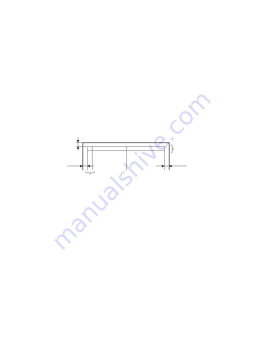
5. Check the gap of the print pattern from the paper edge. (Refer to the <Figure>)
6. Perform the Service Mode F6-04 (Printer Registration) to adjust the gap to be 5 mm.
7. If the gap is less than 5 mm, input a (-) value. If more than 5 mm, input a (+) value.
8. Press the
“Stop”
key first and press the
“Function”
,
“Clear”
keys sequentially to exit the Service
Mode.
3.6.2.
LSU Image Side to Side Adjustment for the Tray
1. Insert Letter or A4 size paper into the 1st tray and change the tray setting to the appropriate paper size.
Empty all the remaining trays (including the bypass tray) to disable them.
Note:
Do not pull out the 1st tray to disable it when adjusting the 2nd tray. The 1st tray is required as it acts
as a paper path for the paper in the 2nd tray.
2. Press the
“Function”
,
“Original Size”
, and the
“3”
keys sequentially.
3. Input the ID, and press the
“Set”
key to enter the Service Mode (default ID is
00000000
).
4. Perform the Service Mode F1-03 (Print Test Pattern 1).
5. Check the gap of the print pattern from the paper edge. (Refer to the "3.6.1. <Figure>")
6. Perform the Service Mode F6-10 to F6-12, to adjust the gap to be 5 mm.
7. If the gap is less than 5 mm, input a (+) value. If more than 5 mm, input a (-) value.
8. Press the
“Stop”
key first and press the
“Function”
,
“Clear”
keys sequentially to exit the Service
Mode.
3.6.3.
ADF Original Read Edge & ADF Main Scan Adjustments
1. Place the Original Document on the ADF.
2. Insert Letter or A4 size paper into the 1st tray and change the tray setting to the appropriate paper size.
Empty all the remaining trays (including the bypass tray) to disable them.
3. Press the
“Function”
,
“Original Size”
, and the
“3”
keys sequentially.
4. Input the ID, and press the
“Set”
key to enter the Service Mode (default ID is
00000000
).
<Figure>
Two lines are printed on the top (Lead edge).
For Letter or A4, place as Portrait.
5 mm
Top (Lead edge)
Two lines are printed
5 mm
5 mm
Two lines are printed
Содержание UF-8300
Страница 5: ...5...
Страница 10: ...10...
Страница 11: ...11...
Страница 12: ...12...
Страница 232: ...232 UF 7300 7200 UF 8300 8200 memo...
Страница 233: ...DZSD001829 15 Panasonic Software Operating Instructions Network Firmware Update Tool for Service Technicians Version 3...
Страница 246: ...Network Firmware Update Tool LAN Page 14 13 Confirm the message in the text box and click OK to close the tool or...
Страница 247: ...DZSD000965 18 Panasonic Software Operating Instructions Local Firmware Update Tool for Service Technicians Version 3...
Страница 261: ...Published in Japan...


