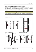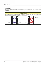
Protection Area
© Panasonic Industrial Devices SUNX Co., Ltd. 2020
25
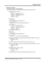
When using as a safety device for a press machine in Japan
[Japan: Power Press Machine Structural Standards]
<Safety distance (reference)>
The safe distance formula given in "Power Press Machine Structural Standards" (including Dec. 26,
1977; Ministry of Labor Notification No. 102, Jan. 12, 2011; Ministry of Health, Labour and Welfare
Notification No. 4) based on the rules of Article 44 is indicated below. The example below provides
values for reference.
For actual installation of a light beam press machine safety device on a press machine, install in ac-
cordance with "Power Press Machine Structural Standards".
Formula (from Article 43 of Power Press Machine Structural Standards)
D = 1.6 × (T
L
+ T
S
) + C
D, T
L
, and T
S
in the above equation indicate the following values.
D : Distance between beam axis of light beam press machine safety device and danger limit (danger
source) (mm)
T
L
: Time from blocking of beam until activation of emergency mechanism of press machine
[Activation delay time of this device (6 to 18msec)]
T
S
: Time from activation of emergency mechanism of press machine until slide stops (ms)
C : Additional distance (mm)
When continuous blocking width is 30mm or less: C = 0 (
SF4D-F□-01
,
SF4D-H□-01
)
When continuous blocking width is 35 to 45mm: C = 300 (
SF4D-A□-01
)
The safe distance (D) is calculated from the formula and the installation distance (A) is thereby de-
termined; however, if the horizontal distance between the light beam and the front line of the bolster
exceeds 400mm, or if the distance does not exceed 400mm but there is a possibility that a worker will
enter the area between the light beam and the bolster, an auxiliary beam channel or additional guard
must be installed.
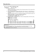
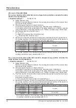
<Calculation example>
When the
SF4D-H16-01
is used and the maximum stopping time of the press machine is 200ms.
Response time of
SF4D-H16-01
: 6ms
D = 1.6 × (200 + 6) + 0
= 329.6 (mm)
The safe distance in this case is D = 329.6 (mm).
<Auxiliary beam channel installation method>
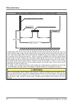
We recommend that you connect the devices used for the primary beam channel (main sensor) and
auxiliary beam channel (sub sensor) in series. A series connection enables prevention of mutual inter-
ference.
1.
If there is sufficient space for a worker to enter the area between the primary beam axis (main sen
-
sor) of the light beam press machine safety device (installed so as to maintain the safe distance)
and the front line of the bolster, install auxiliary beam channels (sub sensors) so that the horizon-
tal distance between the primary beam channel (main sensor) and auxiliary beam channels (sub
sensors) is 75mm or less, and the horizontal distance between the bolster and the auxiliary beam
channel (sub sensors) closest to the bolster is 75mm or less.
2.
Install the auxiliary beam channels (sub sensors) so that they are horizontal with respect to the
front line of the bolster, and in a position that is about the height of the worker's waist.
Содержание SF4D-*-01 Series
Страница 2: ... Panasonic Industrial Devices SUNX Co Ltd 2020 2 MEMO ...
Страница 6: ... Panasonic Industrial Devices SUNX Co Ltd 2020 6 MEMO ...
Страница 120: ...Functions Panasonic Industrial Devices SUNX Co Ltd 2020 120 MEMO ...
Страница 134: ...Troubleshooting Panasonic Industrial Devices SUNX Co Ltd 2020 134 MEMO ...
Страница 168: ... Panasonic Industrial Devices SUNX Co Ltd 2020 168 MEMO ...

