Troubleshooting
© Panasonic Industrial Devices SUNX Co., Ltd. 2020
127
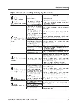
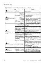
<Digital indicator shows a blinking or steadily lit yellow number>
Cause
Remedy
[“ ” lights]
Error in device settings.
Internal failure
Contact our office.
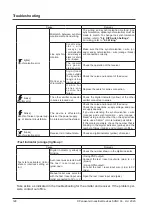
[“ ” blinks]
Error in the number of beam
channels
The device is affected by
noise or the power supply.
An internal circuit has failed.
• Check the noise environment of the device.
• Check the connections, supply voltage, and
power supply capacity.
• Replace the device.
[“ ” blinks]
Series connection error, er-
ror in total number of beam
channels
The number of sensors in se-
ries connection exceeds the
specified limit.
Limit the number of sensors in series connection
to 5 or less.
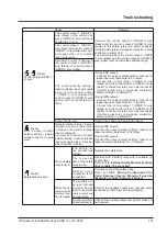
The total number of beam
channels of the sensors in
series connection exceeds
the specified limit.
Limit the total number of beam channels to 256
or less.
Incorrect emitter and receiver
connection when connected
in a series connection.
Connect emitters to emitters and receivers to re-
ceivers using a series connection cable.
In a series connection, the
DIP switches 1 / 2 (synchro-
nization method) are not all
set to the same state.
Set all DIP switches 1 / 2 (synchronization meth-
od) to the same state.
End cap is not attached.
Make sure the end cap is installed correctly.
Cable for series connection is
disconnected.
• Make sure the cable for series connection is
connected correctly.
• Replace the cable for series connection.
Another error has generated. Check the operation of other sensors in series
connection.
[“ ” blinks]
Emitter and receiver system
mismatch.
The emitter system and re-
ceiver system do not match.
Make sure the beam pitch, number of sensors
and number of beam channels of the emitter and
receiver match.
Connect the output polarity setting / lockout re-
lease input wires (pale blue) of the emitter and
receiver in the same way.
• Using PNP output: Connect to 0V (blue)
• Using NPN output: Connect to + V (brown)
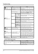
[“ ” blinks]
Error in wiring of output po-
larity setting / lockout release
input wire (pale blue).
Output polarity setting / lock
-
out release input wire (pale
blue) is broken or shorted to
another input / output wire.
Incorrect connection of out-
put polarity setting / lockout
release input wire (pale blue)
on receiver side of emitter /
receiver.
<Using PNP output>
Connect the output polarity setting / lockout re-
lease input wire (pale blue) to 0V (blue).
<Using NPN output>
Connect the output polarity setting / lockout re-
lease input wire (pale blue) to + V (brown).
[“ ” blinks]
Power supply voltage error
The voltage of the power sup-
plied to the device exceeds
the specified range.
Make sure the power supply voltage conforms to
the specification.
[“ ” blinks]
Muting auxiliary output error
Output is shorted to another
input / output wire.
Use the muting auxiliary output at a current from
250mA or less.
Excessive rush current in the
muting auxiliary output.
Output circuit error.
Output circuit damage.
Replace the device.
Содержание SF4D-*-01 Series
Страница 2: ... Panasonic Industrial Devices SUNX Co Ltd 2020 2 MEMO ...
Страница 6: ... Panasonic Industrial Devices SUNX Co Ltd 2020 6 MEMO ...
Страница 120: ...Functions Panasonic Industrial Devices SUNX Co Ltd 2020 120 MEMO ...
Страница 134: ...Troubleshooting Panasonic Industrial Devices SUNX Co Ltd 2020 134 MEMO ...
Страница 168: ... Panasonic Industrial Devices SUNX Co Ltd 2020 168 MEMO ...

