115
9.4.
Scanner Self-test
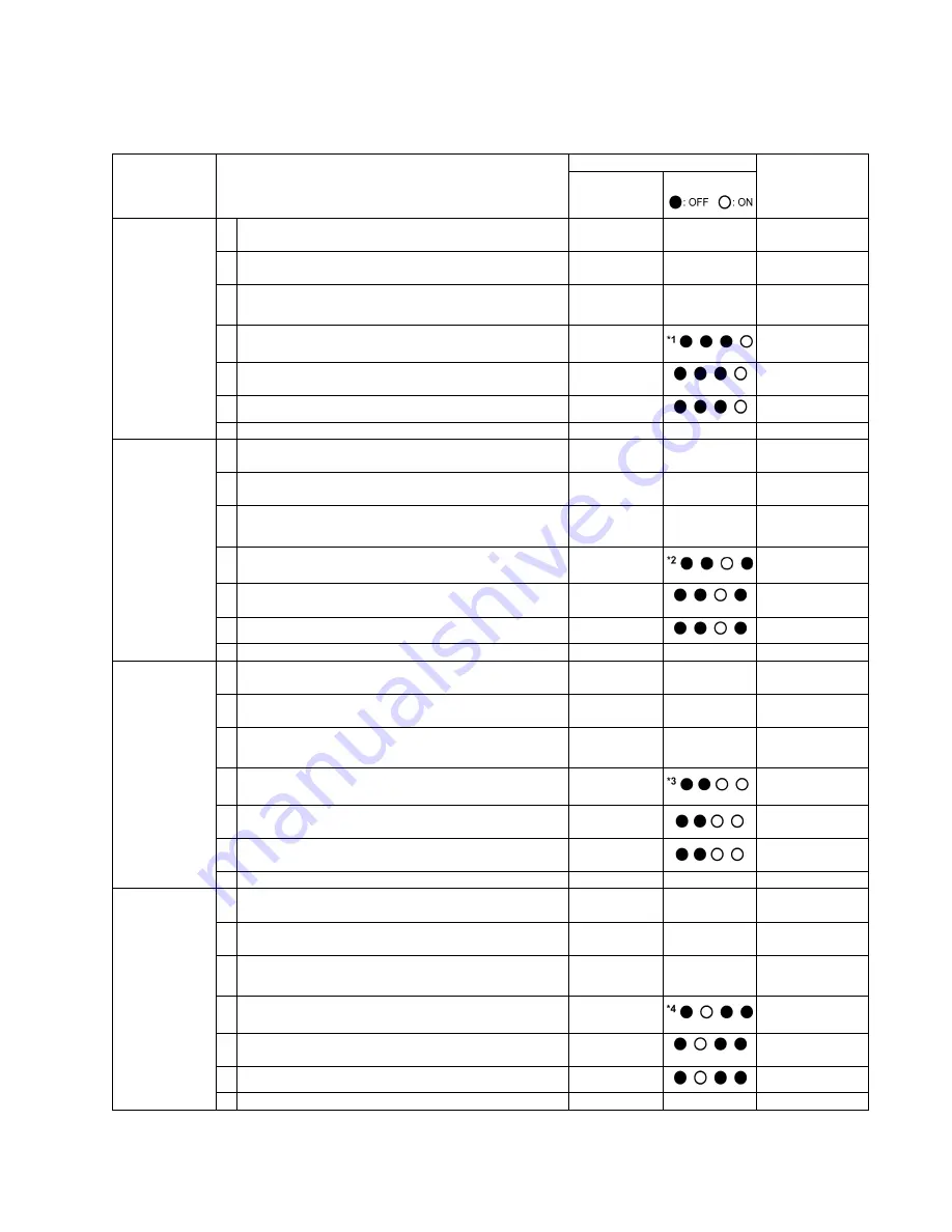
Without connecting the scanner to the PC, the following scanner self-test can be performed. The following mechanical test is
generally used after replacing or reassembling rollers (Drive Rollers) and other mechanical parts related to feeding documents.
Test Item
Operation
LED or Indicator Status
Remarks
*8
Indicators
(Control Panel)
*8
LED (Back)
1. Paper Feed
Motor rotation
1 While pushing the
“START/STOP Key”
on the Control
Panel, turn on the scanner.
—
—
2 Release the key after LED (Back) status changes to
blinking.
OFF
Blinking
3 Push the “
START/STOP Key
” once to enter the test
selection mode.
Blinking
Count
4 Push the
“START/STOP Key”
once at the timing when
LED (Back) status is 1 (h)
*1
.
5 Push the
“START/STOP Key”
to start rotating the
Paper Feed Motor and Separation Motor.
6 Push the
“START/STOP Key”
to stop the rotating.
7 Turn off the scanner to finish this test.
—
—
2. Conveyor
Motor rotation
1 While pushing the
“START/STOP Key”
on the Control
Panel, turn on the scanner.
—
—
2 Release the key after LED (Back) status changes to
blinking.
OFF
Blinking
3 Push the “
START/STOP Key
” once to enter the test
selection mode.
Blinking
Count
4 Push the
“START/STOP Key”
once at the timing when
LED (Back) status is 2 (h)
*2
.
5 Push the
“START/STOP Key”
to start rotating the
Conveyor Motor.
6 Push the
“START/STOP Key”
to stop the rotating.
7 Turn off the scanner to finish this test.
—
—
3. DFP Pressure
Motor rotation
1 While pushing the
“START/STOP Key”
on the Control
Panel, turn on the scanner.
—
—
2 Release the key after LED (Back) status changes to
blinking.
OFF
Blinking
3 Push the “
START/STOP Key
” once to enter the test
selection mode.
Blinking
Count
4 Push the
“START/STOP Key”
once at the timing when
LED (Back) status is 3 (h)
*3
.
5 Push the
“START/STOP Key”
to start rotating the
DFP Pressure Motor.
6 Push the
“START/STOP Key”
to stop the rotating.
7 Turn off the scanner to finish this test.
—
—
4. Hopper Drive
1 While pushing the
“START/STOP Key”
on the Control
Panel, turn on the scanner.
—
—
2 Release the key after LED (Back) status changes to
blinking.
OFF
Blinking
3 Push the “
START/STOP Key
” once to enter the test
selection mode.
Blinking
Count
4 Push the
“START/STOP Key”
once at the timing when
LED (Back) status is 4 (h)
*4
.
5 Push the
“START/STOP Key”
to start to execute the
open/close operation of the gate.
6 Push the
“START/STOP Key”
to stop the rotating.
7 Turn off the scanner to finish this test.
—
—
Содержание KV-S5046H
Страница 8: ...8 3 COMPONENT IDENTIFICATION 3 1 Main Part Names and Locations ...
Страница 9: ...9 ...
Страница 19: ...19 5 SECTIONAL VIEW 5 1 Bottom Block ...
Страница 20: ...20 5 2 Back Block ...
Страница 21: ...21 5 3 Upper Block ...
Страница 22: ...22 5 4 Lower Block 5 4 1 Mechanical Parts ...
Страница 23: ...23 5 4 2 Boards ...
Страница 39: ...39 Location of Reflectors G G G Reflectors ...
Страница 48: ...48 ...
Страница 49: ...49 ...
Страница 57: ...57 3 The decomposition procedure of CIS 3 1 Check the Hook 3 2 Unhook 5 points Hook 3 3 Lift up Glass ASSY ...
Страница 76: ...76 3 Remove the screw 4 While releasing the 3 claws pull the Left Cover forward ...
Страница 79: ...79 5 Pull in each directions and remove rubber parts 6 Component Parts ...
Страница 86: ...86 5 Disconnect the connector 6 Pull and remove the Conveyor Motor ...
Страница 89: ...89 6 Disconnect the Flat cable 7 Remove the CIS B 8 Remove Glass Assy See 8 4 2 ...
Страница 92: ...92 4 Pull out the Drive Roller 2 in the direction of the arrow ...
Страница 104: ...104 ...
Страница 132: ...132 ...
Страница 133: ...133 ...
Страница 134: ...134 ...
Страница 224: ...224 14 PARTS LOCATION AND MECHANICAL PARTS LIST ...
Страница 241: ...241 14 7 Packing 466 468 461 462 464 467 467 456 457 460 463 465 469 458 459 ...


