30
6.6.
Mechanical Deskew Mechanism (KV-S5076H only)
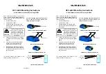
Deskew Correction is performed by the Drive Roller 1.
1.Detect the Skew of the document.
2.Adjust the skewed document direction by different Roller rotation speed between Left and Right Roller. (Deskew)
* Only Right Drive Roller can change its speed.
Detect the skew in documents by Waiting Sensor and Skew Sensors L/ R.
Adjust the skewed documents by changing rotation speed of Drive Roller 1 R mounted at the right side independently.
<Procedure of document adjustment by Mechanical deskew >
1.Convey the documents by Feed Roller
2.Separate each document by Separation Roller.
3.Detect the skew in documents by three sensors.
4.Adjust the skewed documents by changing rotation speed of Drive Roller 1 R
mounted at the right side independently.
* The Drive Roller 1 L keeps same rotation speed.
Skew Sensors detect the skew in documents.
DFP roller
Exit tray
CIS Front
Feed Tray
Feed Roller
CIS Back
Separation Roller
Skew Sensor
Drive Roller 1
Exit Roller
Drive Roller 2
Drive Roller 3
Feed Roller
Drive Roller 1 R
Separation Roller
Skew Sensor L
Drive Roller 1 L
Skew Sensor R
Waiting Sensor
Feeding Direction
Содержание KV-S5046H
Страница 8: ...8 3 COMPONENT IDENTIFICATION 3 1 Main Part Names and Locations ...
Страница 9: ...9 ...
Страница 19: ...19 5 SECTIONAL VIEW 5 1 Bottom Block ...
Страница 20: ...20 5 2 Back Block ...
Страница 21: ...21 5 3 Upper Block ...
Страница 22: ...22 5 4 Lower Block 5 4 1 Mechanical Parts ...
Страница 23: ...23 5 4 2 Boards ...
Страница 39: ...39 Location of Reflectors G G G Reflectors ...
Страница 48: ...48 ...
Страница 49: ...49 ...
Страница 57: ...57 3 The decomposition procedure of CIS 3 1 Check the Hook 3 2 Unhook 5 points Hook 3 3 Lift up Glass ASSY ...
Страница 76: ...76 3 Remove the screw 4 While releasing the 3 claws pull the Left Cover forward ...
Страница 79: ...79 5 Pull in each directions and remove rubber parts 6 Component Parts ...
Страница 86: ...86 5 Disconnect the connector 6 Pull and remove the Conveyor Motor ...
Страница 89: ...89 6 Disconnect the Flat cable 7 Remove the CIS B 8 Remove Glass Assy See 8 4 2 ...
Страница 92: ...92 4 Pull out the Drive Roller 2 in the direction of the arrow ...
Страница 104: ...104 ...
Страница 132: ...132 ...
Страница 133: ...133 ...
Страница 134: ...134 ...
Страница 224: ...224 14 PARTS LOCATION AND MECHANICAL PARTS LIST ...
Страница 241: ...241 14 7 Packing 466 468 461 462 464 467 467 456 457 460 463 465 469 458 459 ...


