114
9.3.9.
Other (Save Information)
Click
“Save Info”
on the main menu to save the scanner and the PC information as text files.
* USB ID
1. Click
“USB ID”
on the main menu to enter the
“USB ID”
dialog box.
2. Click
“Set”
on the
“USB ID”
dialog box to store a new ID
number for a new replaced CONTROL Board.
3. Click
“Close”
to return to the main menu.
—
*This setting is available only
for a new replaced
CONTROL Board or IC0004.
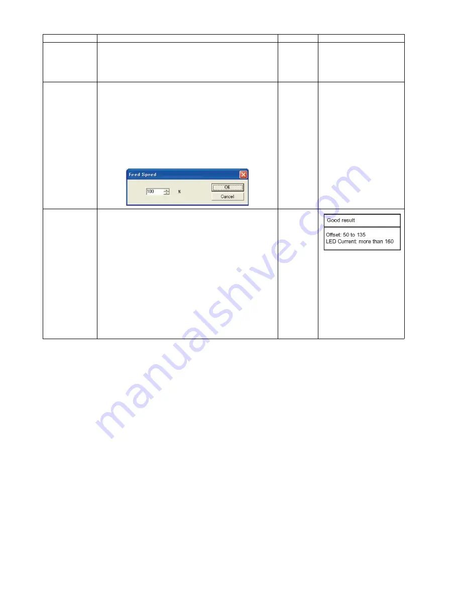
Feed Speed
1. Click
“Feed Speed”
on the main menu.
2. Change the parameter (%: 10 to 100).
3. Click
“OK”
to renew the setting, and to return to the main
menu.
Note:
1. Reducing the Feed Speed to slow may reduce the
number of paper-jams or double-feeds.
2. Setting this parameter to too low may cause
a paper-feed problem. After changing the
parameter, make sure to perform the scanning test,
and to confirm that paper-jams do not occur.
100 %
Sensor Sensitive
Level
1. Click
“Sensor Sensitive Level”
on the main menu.
Note:
The adjustment is done for all the sensors below at
a time.
Waiting Sensor, Slip Detect Sensor, Starting Sensor,
Ending Sensor, Skew(R) Sensor*, Skew(L) Sensor*.
*KV-S5076H only
So be sure to clean before adjusting and remove dust
thoroughly from the sensors and reflectors at the oppo-
site side with a cotton swab.
*If dust remains on them, the adjustment is not done
properly and the paper detection may not be able to
work.
2. Click
“Adjust”
on the
“Sensor Sensitive Level”
dialog box to adjust
the sensor Sensitive level. Check each sensor’s sensitive level
(Offset, LED Current, Slice) on the Sensor Sensitive Level dialog box.
3. Click
“Close”
to return to the main menu.
Item
Operation
Default
Remarks
Содержание KV-S5046H
Страница 8: ...8 3 COMPONENT IDENTIFICATION 3 1 Main Part Names and Locations ...
Страница 9: ...9 ...
Страница 19: ...19 5 SECTIONAL VIEW 5 1 Bottom Block ...
Страница 20: ...20 5 2 Back Block ...
Страница 21: ...21 5 3 Upper Block ...
Страница 22: ...22 5 4 Lower Block 5 4 1 Mechanical Parts ...
Страница 23: ...23 5 4 2 Boards ...
Страница 39: ...39 Location of Reflectors G G G Reflectors ...
Страница 48: ...48 ...
Страница 49: ...49 ...
Страница 57: ...57 3 The decomposition procedure of CIS 3 1 Check the Hook 3 2 Unhook 5 points Hook 3 3 Lift up Glass ASSY ...
Страница 76: ...76 3 Remove the screw 4 While releasing the 3 claws pull the Left Cover forward ...
Страница 79: ...79 5 Pull in each directions and remove rubber parts 6 Component Parts ...
Страница 86: ...86 5 Disconnect the connector 6 Pull and remove the Conveyor Motor ...
Страница 89: ...89 6 Disconnect the Flat cable 7 Remove the CIS B 8 Remove Glass Assy See 8 4 2 ...
Страница 92: ...92 4 Pull out the Drive Roller 2 in the direction of the arrow ...
Страница 104: ...104 ...
Страница 132: ...132 ...
Страница 133: ...133 ...
Страница 134: ...134 ...
Страница 224: ...224 14 PARTS LOCATION AND MECHANICAL PARTS LIST ...
Страница 241: ...241 14 7 Packing 466 468 461 462 464 467 467 456 457 460 463 465 469 458 459 ...


