Chapter 4
Settings — [Layouts]
52 - ENGLISH
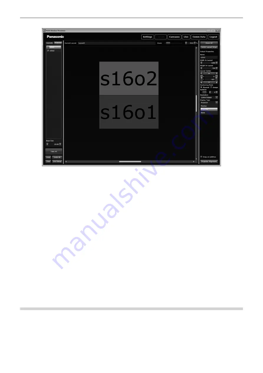
Before setting edge blending, check that [Display Type] is set to [Projector].
1) Click the [Projector Alignment] button in the setting area.
f
The display items in the setting area change, and the
[Projector Alignment]
screen is displayed.
f
The positions of output devices in the layout window are locked so that they cannot be dragged with the mouse.
2) Adjust [Edge Alignment]. (
x
page 52)
f
Arrange projectors correctly, and perform the initial setting of blending for the overlapping portion of images.
3) Click the [Linearity Correction] button.
f
The setting items of [SCurve] are displayed in the setting area.
4) Perform S-curve correction with [SCurve]. (
x
page 53)
5) When S-curve correction is completed, click the [SCurve] button.
f
The setting items of [SCurve] in the setting area change to the setting items of [Gamma].
6) Perform gamma correction with [Gamma]. (
x
page 54)
7) Click the [Black Level Boost] button.
f
The setting items of [Black Level Boost] are displayed in the setting area.
8) Adjust [Black Level Boost]. (
x
page 54)
9) Click the [Projector Alignment] button.
f
When all adjustments are completed, release the lock performed in Step
1)
.
10) Click the [Take All] button.
f
All settings of the newly configured layout are sent to this device. If there are other outputs, a maximum four layouts can be configured.
[Edge Alignment]
Arrange projectors correctly, and perform the initial setting of blending for the overlapping portion of images. Each time an output device is
clicked, active (red) and inactive (green) switch.
When two adjacent output devices are activated (red), they are displayed as one group of arrangement in the output list. The outer border line
is displayed in green for both the selected output devices, and the inner red line is displayed at the joint between projectors.
Perform position adjustment or lens adjustment of each projector automatically using these lines to correct the arrangement of projectors.
Perform this operation to confirm that the size of projection images are the same using the green box, and that the red and green lines are
parallel to each other and they are projected on the screen making one yellow line.


