Chapter 2
Getting Started — Connecting
ENGLISH - 27
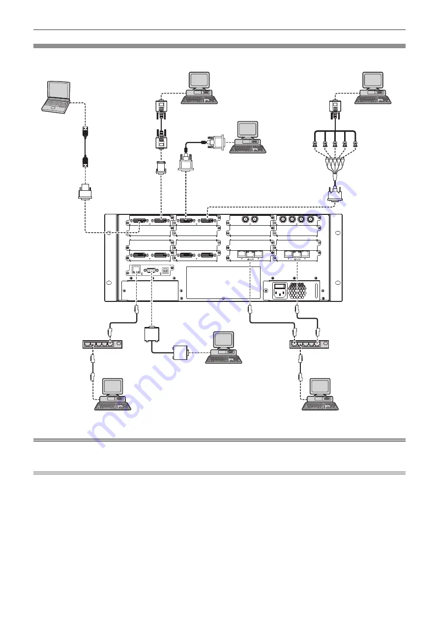
Connecting example: Computers
The following example shows the optional Interface Board for DVI-U 2input (Model No. ET-MCYDV100) attached to
Slot1
and
Slot2
, Interface
Board for Digital Link 2output (Model No. ET-MCQDL350) to
Slot15
and
Slot16
on the slot section of this device.
HD-SDI INPUT
ST
HD-SDI INPUT
3
1
2
4
3G-SDI INPUT
ST
3G-SDI INPUT
1
2
DVI-U INPUT
STATUS
DVI-U INPUT
DVI-U INPUT
STATUS
DVI-U INPUT
DVI-U SCALED OUTPUT
STATUS
DVI-U SCALED OUTPUT
DVI-U SCALED OUTPUT
STATUS
DVI-U SCALED OUTPUT
DIGITAL
LINK
DIGITAL
LINK
DIGITAL
LINK
DIGITAL
LINK
1
2
3
4
USB
RS232
LAN
Computer
Computer
Hub
Computer for controlling this device
Computer
Computer for controlling this device
Computer for display control
DVI - HDMI conversion
adaptor (commercially
available)
Hub
DVI - D-Sub conversion
adaptor (commercially
available)
Computer
DVI - RGBHV (5 BNC) conversion adaptor
(commercially available)
Attention
f
To assure continued performance and FCC compliance, use only high quality DVI-D interface cable with two ferrite cores for connecting with
the <DVI-U INPUT> terminal.
Note
f
The <DVI-U INPUT> terminal can be connected to HDMI and DVI-I-compatible devices. However, images may not appear or may not be
displayed properly on some devices.
f
For an HDMI cable, use an HDMI High Speed cable that conforms to HDMI standards. If a cable that does not conform to HDMI standards
is used, image may be interrupted or may not be displayed.
f
The <DVI-U INPUT> terminal (for digital input) only supports a single link.
f
For the serial cable that would connect to the <RS232> terminal, use a straight-through cable.
f
When connecting the control computer to the <LAN> terminal on the CPU board section and the <LAN> terminal on the Interface Board for
Digital Link 2output (Model No. ET-MCQDL350) via a LAN cable, use a crossover cable. When using network devices, such as a hub, use
straight-through cables.


